AP1720-E1
advertisement
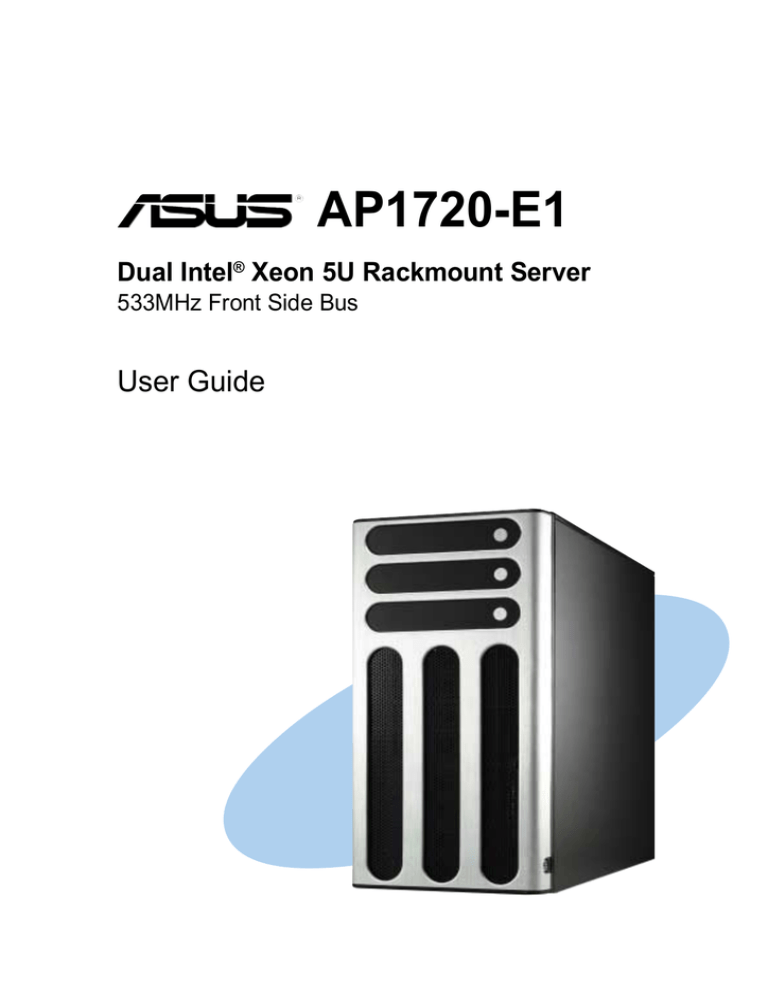
AP1720-E1 Dual Intel® Xeon 5U Rackmount Server 533MHz Front Side Bus User Guide This chapter describes the general features of the barebone server. It includes sections on front panel and rear panel specifications. ASUS AP1720-E1 user guide Product introduction Chapter 1 1-1 1.1 System package contents Check your ASUS AP1720-E1 package with the items on the following table. The package contents vary for 8-SCSI, 4-SCSI, and 4-IDE HDD configurations. Contact your dealer immediately if any of the items is damaged or missing. HDD Bays Item Description AS8 (8 SCSI ) AS4 (4 SCSI) AI4 (4 IDE) 1) ASUS AK25 5U rackmount chassis with: • ASUS PC-DL Deluxe motherboard • 450W power supply • SCSI backplane board (2 pieces) (1 piece) • ASUS U160/320 SCSI card/SCSI cable • 52x CD-ROM drive • floppy disk drive • chassis fan • HDD fan (2 units) (1 unit) • hot-swap SCSI HDD trays (8 units, including screws for HDDs) (4 units, including screws for HDDs) • internal HDD rails (4 pairs) • chassis roller wheels (4 sets) • CPU heatsink and fan assembly (2 sets) • front I/O board • HDD dummy covers (for IDE bays) 2) AC power cable 3) System screws and cables 4) System keys ( 2 pcs.) 5) Bundled CDs • AP1720-E1 support CD • ASWM software CD • TrendMicro® ServerProtect® CD 6) Documentation • ASUS AP1720-E1 user guide • ASUS PC-DL Deluxe user guide 7) Optional items • ASUS AK25 rackmount rail kit • AK25 internal HDD cage (non-hot swap) 1-2 Chapter 1: Product introduction 1.2 System specifications The ASUS AP1720-E1 is a barebone server system featuring the ASUS PC-DL Deluxe motherboard. The server supports dual Intel® Xeon™ processors in 604-pin sockets, and includes the latest technologies through the chipsets embedded on the motherboard. Chassis Pedestal or rackmount 5U with removable front door bezel and chassis foot stand or roller-wheels. Motherboard ASUS PC-DL Deluxe (ATX form factor: 12 in x 9.6 in) Chipset Intel® 82875 Memory Controller Hub (MCH) Intel® 82801ER I/O Controller Hub (ICH5R) Processor Supports dual Intel® Xeon™ CPUs up to 3.06+ GHz with 533MHz FSB Memory 4 x 184-pin DDR sockets for up to 4GB memory Supports PC2700/PC2100 unbuffered ECC or non-ECC DDR DIMMs LAN Intel® 82547EI Gigabit LAN controller IEEE 1394 TI TSB43AB22A IEEE 1394 controller RAID Promise® PDC20378 controller (supports RAID 0/RAID 1/RAID 0+1/Multi-RAID) Expansion slots 1 x AGP Pro/8X slot 5 x 32-bit/33Mhz 5V PCI slots Drive bays 1 x 3.25-inch FDD bay 3 x 5.25-inch drive bays Front I/O 4 x USB 2.0 1 x IEEE 1394 port Line Out/Microphone ports Rear panel I/O 1 x Parallel port 2 x Serial ports 1 x RJ-45 port 1 x IEEE 1394 port 4 x USB 2.0 ports 1 x PS/2 keyboard port 1 x PS/2 mouse port Line In/Line Out/Microphone ports Management ASUS Server Web-based Management (ASWM) 2.0 Hardware monitors Voltage, temperature, and fan speed monitoring Automatic System Restart (ASR) feature Power supply SSI-type 450W power supply (with 24-pin and 8-pin power plugs) * Refer to the motherboard user guide for more information on internal connectors. ASUS AP1720-E1 barebone server 1-3 1.3 Front panel features The AP1720-E1 chassis displays a stylish front bezel with lock. The bezel covers the system components on the front panel and serves as security. Open the bezel to access the front panel components. The drive bays, power and reset buttons, LED indicators, CD-ROM drive, floppy drive, and four USB ports are located on the front panel. For future installation of 5.25-inch devices, two drive bays are available. CD-ROM drive 2 empty 5.25-inch bays Power button Reset button Message LED HDD access LED Power LED Floppy disk drive IEEE 1394 port 4 USB 2.0 ports Microphone jack Line Out jack Drive bays Security lock 1-4 Chapter 1: Product introduction If you wish to access front I/O ports and floppy disk drive without opening the bezel, hold the tab and move the sliding panel (rightmost panel) to the left as shown. 1.4 Rear panel features The rear panel includes a slot for the motherboard rear I/O ports, expansion slots, a chassis lock and intrusion switch, a vent for the system fan, and power supply module. Power supply module P/S2 mouse port P/S2 keyboard port Parallel port Serial ports Power connector 12cm fan vent Chassis lock IEEE 1394 port 4 USB 2.0 ports Gigabit LAN port Audio ports Expansion slots SCSI port (optional) ASUS AP1720-E1 barebone server 1-5 1.5 Internal features The barebone server system includes the basic components as shown. AS8 (8-SCSI configuration) 2 1 3 8 10 6 4 7 5 9 1. 2. 3. 4. 5. Power supply cage CD-ROM drive 2 x 5.25-inch drive bays first drive cage (upper) second drive cage (lower) 6. HDD fan 1 7. HDD fan 2 (optional) 8. Chassis fan 9. Expansion card lock 10. PC-DL Deluxe motherboard The lower 4-bay hot swap SCSI drive cage may be changed to an internal IDE drive cage (non-hot swap) if you wish to install long PCI cards. The internal drive cage is optional and purchased separately. 1-6 Chapter 1: Product introduction AS4 (4-SCSI configuration) AI4 (4-IDE configuration) ASUS AP1720-E1 barebone server 1-7 1.6 LED information The barebone system comes with five LED indicators. Refer to the following table for the LED status description. Power LED (blue) HDD Access LED (green) ! Message LED (red) Drive status LED (green/red) Drive activity LED LED Icon Display status Description System Power LED ON Blinking System power ON Suspend mode HDD Access LED OFF Blinking No activity Read/write data into the HDD OFF Blinking System is normal; no incoming event ASMS indicates a HW monitor event Green Bridge board connected to backplane Installed HDD is in good condition HDD failure HDD rebuilding using the RAID card SAF-TE* function Message LED ! Hard disk drives Drive Status LED Red Red-Blinking Drive Activity LED Blinking Read/write data into the HDD *SCSI Access Fault-Tolerant Enclosure The Power, HDD Access, and Message LEDs are visible even if the system front bezel is closed. 1-8 Chapter 1: Product introduction Appendix Power supply This appendix gives information on the power supply that came with the barebone server. ASUS AP1720-E1 barebone server 3-1 A.1 General description The server comes with an SSI-type 450W ATX power supply with universal AC input that includes PFC and ATX-compliant output cables and connectors. The power supply has nine plugs labeled P1 to P10 (no P3). Take note of the devices to which you should connect the plugs. P1 P1 P2 P4 P5 P6 P7 P8 P9 P10 A-2 P2 P4 P5 P6 P7 P8 P9 P10 Motherboard 24-pin ATX power connector Motherboard 8-pin +12V AUX power connector Floppy disk drive Peripheral device (second backplane, if present) Peripheral device (available) Peripheral device (second backplane, if present) Peripheral device (first backplane, if present) Peripheral device (first backplane, if present) Peripheral device (optical drive) Chapter 3: Installation options A.2 Specifications Output voltage regulation Output Voltage Min (V) Nom (V) Max (V) +3.33V 3.16 3.30 3.46 50mVp-p 4.8 5.00 5.25 50mVp-p +12V 11.52 12.00 12.60 120mVp-p -12V -11.4 -12.20 -13.08 120mVp-p 4.8 5.00 5.25 50mVp-p +5V +5VSB Ripple/Noise Output current capacity Output Voltage Min (A) Max (A) Max. Load (W) +3.33V 0.5 24.0 79.0 +5V 2.0 20.0 100.0 +12V 4.0 30.0 360.0 -12V 0.0 0.5 6.0 +5VSB 0.1 2.0 10 Over-voltage protection Voltage Min (V) +3.33V 3.9 4.5 +5V 5.7 6.5 +12V 13.3 15.0 +12V -13.3 -15.0 5.7 6.5 +5VSB Max (V) ASUS AP1720-E1 barebone server A-3
