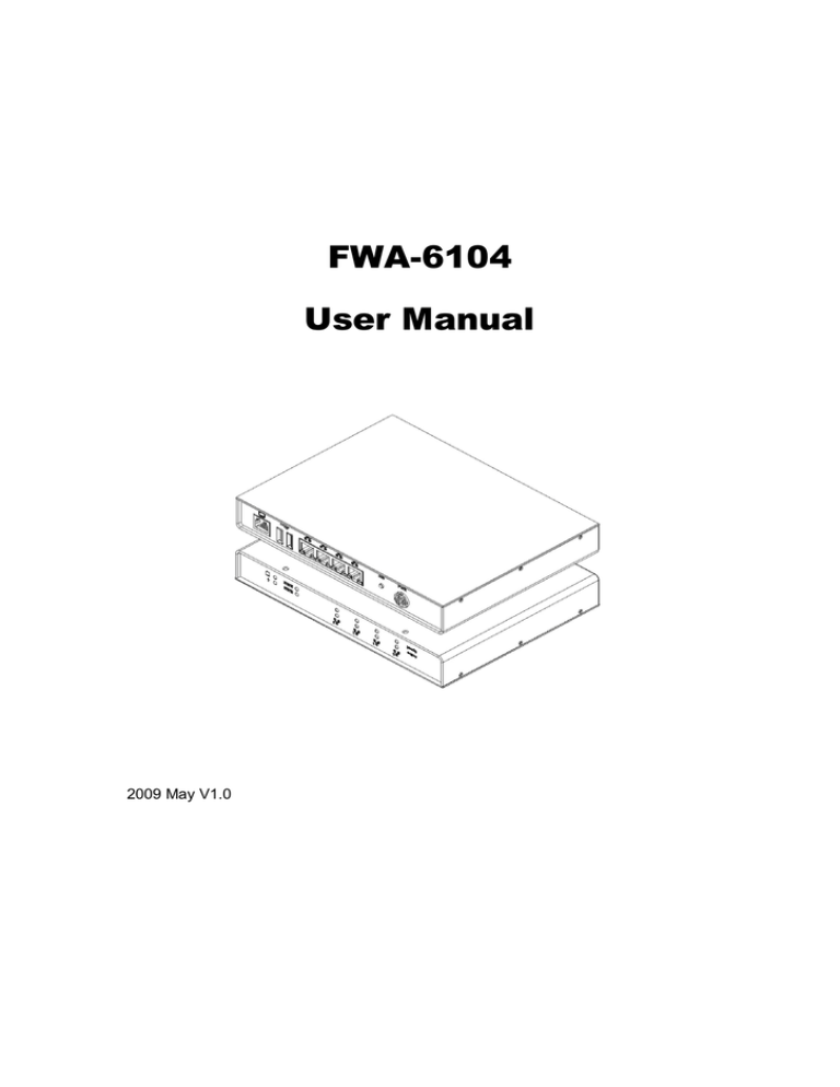
FWA-6104
User Manual
2009 May V1.0
Copyright © 2008 IBASE Technology INC. All Rights Reserved.
No part of this manual, including the products and software described in it, may be
reproduced, transmitted, transcribed, stored in a retrieval system, or translated into
any language in any form or by any means, except documentation kept by the
purchaser for backup purposes, without the express written permission of IBASE
Technology INC. (“IBASE”).
Products and corporate names mentioned in this manual may or may not be
registered trademarks or copyrights of their respective companies, and are used for
identification purposes only. All trademarks are the property of their respective
owners.
Every effort has been made to ensure that the contents of this manual are correct and
up to date. However, the manufacturer makes no guarantee regarding the accuracy of
its contents, and reserves the right to make changes without prior notice.
2
Table of Contents
Accessories ........................................................................................................... 6
Components.......................................................................................................... 7
Front View ................................................................................................................... 7
Rear View .................................................................................................................... 8
Specification ......................................................................................................... 9
Exploded view of the FWA-6104 assembly ............................................................10
Parts description ........................................................................................................ 10
Driver Installation ................................................................................................11
BIOS Setup ...........................................................................................................11
3
Safety Information
Your FWA-6104 is designed and tested to meet the latest standards of safety for
information technology equipment. However, to ensure your safety, it is important that
you read the following safety instructions.
Setting up your system
•
Read and follow all instructions in the documentation before you operate your
system.
•
Do not use this product near water.
•
Set up the system on a stable surface or secure on wall with the provided rail. Do
not secure the system on any unstable plane or without the rail.
•
Do not place this product on an unstable cart, stand, or table. The product may
fall, causing serious damage to the product.
•
Slots and openings on the chassis are for ventilation. Do not block or cover these
openings. Make sure you leave plenty of space around the system for ventilation.
Never insert objects of any kind into the ventilation openings.
•
This system should be operated from the type of power indicated on the marking
label. If you are not sure of the type of power available, consult your dealer or
local power company.
•
Use this product in environments with ambient temperatures between 0˚C and
45˚C.
•
If you use an extension cord, make sure that the total ampere rating of the
devices plugged into the extension cord does not exceed its ampere rating.
Care during use
•
Do not walk on the power cord or allow anything to rest on it.
•
Do not spill water or any other liquids on your system.
•
When the system is turned off, a small amount of electrical current still flows.
Always unplug all power, and network cables from the power outlets before
cleaning the system.
•
If you encounter the following technical problems with the product, unplug the
power cord and contact a qualified service technician or your retailer.
The power cord or plug is damaged.
Liquid has been spilled into the system.
The system does not function properly even if you follow the operating
instructions.
4
The system was dropped or the cabinet is damaged.
Lithium-Ion Battery Warning
CAUTION: Danger of explosion if battery is incorrectly replaced. Replace only with
the same or equivalent type recommended by the manufacturer. Dispose of used
batteries according to the manufacturer’s instructions.
NO DISASSEMBLY
The warranty does not apply to the products that have been disassembled by users
5
Accessories
a. Power Cord x 1
b. M/B Manual x 1
c. Driver CD x 1
d. Console converter cable x 1
e. Power Adapter x 1
f. Rubber Foot x 5
6
Components
Front View
Refer to the diagram below to identify the components on this side of the system.
Active
The LED illuminated when corresponding LAN port transmitted or received data.
Speed
The orange color shows corresponding LAN port connected with Giga-speed.
The Green color shows corresponding LAN port connected with 100-Base-T
speed.
The power LED illuminated when system been power on.
The hard disk LED blinks when data is being written into or read from the hard
disk drive.
Status1 & Status2
There are user programmable indicators. Each indicator can be program to
specify status indicator. The detail programming method please refer M/B user
manual.
7
Rear View
Refer to the diagram below to identify the components on this side of the system.
PWR
The supplied power adapter converts AC power to DC power for use with this
jack. Power supplied through this jack supplies power to the system. To prevent
damage to the system, always use the supplied power adapter.
SW
Reserved.
~
The eight-pin RJ-45 LAN port supports a standard Ethernet cable for connection
to a local network up to Giga-bit transfer rate.
The USB (Universal Serial Bus) port is compatible with USB devices such as
keyboards, mouse devices, cameras, and hard disk drives. USB allows many
devices to run simultaneously on a single computer, with some peripheral acting
as additional plug-in sites or hubs.
There is standard RS232 serial port present by RJ45 connector format. The detail
usage please refers to M/B user manual.
8
Specification
System Mainboard
MB836
Construction
Steel & Aluminum
Chassis Color
Computer light gray
Storage
2.5” SATA HDD x 1(Optional)
Mounting
Desktop / Rack mount (Optional)
Dimensions
207.6(W) x 28.5(H) x 157.5(D)mm / (8.17” x 1.12” x 6.2”)
Power Supply
30W power adapter
Operating Temperature 0°C ~ 45°C (32°F ~ 113°F) still air
Storage Temperature
-20°C ~ 70°C
Relative Humidity
5~95% @45°C (non-condensing)
Vibration
HDD: 0.25g/5~500Hz random operation
Shock
HDD: 15g peak acceleration (11 msec duration)
RoHS
Available
‧This specification is subject to change without prior notice.
9
Exploded view of the FWA-6104 assembly
6
7
8
1
9
2
10
3
4
5
Parts description
Part NO. Description
Part NO.
Description
1 Top Cover
2 HDD Bracket
3 Base Chassis
4 Front Bracket
5 Front Silkscreen Plate
6 MB836
7 2.5” SATA HDD
8 HDD Handle
9 Rear I/O Silkscreen Plate
10 Rear I/O Bracket
10
Driver Installation
Please refer correspond mainboard user manual to install the driver properly.
BIOS Setup
Please refer correspond mainboard user manual to configure BIOS setting.
11

