Design and Implementation of Maximum Power Point
advertisement
International Journal for Research and Development in Engineering (IJRDE)
www.ijrde.com
ISSN: 2279-0500
Special Issue: pp- 012-016
Design and Implementation of Maximum Power Point Tracking
For Super Lift Converter
Indu V. R1; V. Chamundeeswari2
1,2
Department of EEE, St. Joseph’s college of engineering, Chennai, India
ABSTRACT
Photovoltaic (PV) is a technical name in which radiant
(photon) energy from the sun is converted to direct
current (dc) Electrical Energy. PV power output is still
low, continuous efforts are taken to develop the PV
converter and controller for maximum power extracting
efficiency and reduced cost factor. The maximum power
point tracking (MPPT) is a process which tracks one
maximum power point from array input, varying the
ratio between the voltage and current delivered to get
the most power it can. A number of algorithms have
been developed for extracting maximum power. This
paper details the study of incremental conductance
MPPT algorithm with the help of a negative output luo
converter.
Keywords-
PV
Module,
MPPT,
Incremental
Conductance (IC) Algorithm, luo converter.
I.
INTRODUCTION
Solar Energy is the ultimate source of energy, which is
naturally replenished in a short time period of time, for this
reason it is called “Renewable Energy” or “Sustainable
Energy”. Due to the severity of the global energy crisis and
environmental pollution, the photovoltaic (PV) system has
become one kind of important renewable energy source.
Solar energy has the advantages of maximum reserve,
inexhaustibleness, and is free from geographical
restrictions, thus making PV technology a popular research
topic. The efficiency of solar cells depends on many factors
such as temperature, insolation, spectral characteristics of
sunlight, dirt, shadow, and so on. Changes in insolation on
panels due to fast climatic changes such as cloudy weather
and increase in ambient temperature can reduce the
photovoltaic (PV) array output power. In
addressing the poor efficiency of PV systems, some
methods is proposed, among which is a new concept called
“maximum power point tracking” (MPPT). All MPPT
methods follow the same goal which is maximizing the PV
array output power by tracking the maximum power on
every operating condition. In this paper we use incremental
conductance algorithm for precise control under rapidly
changing atmospheric conditions.
II. PV CELL MODELING
A PV module consists of number of solar cells connected in
series and parallel to obtain desired voltage and current.
Each solar cell is basically a p-n diode. As sunlight strikes a
solar cell, the incident energy is converted directly into
electrical energy without any mechanical effort.
Transmitted light is absorbed within the semiconductor by
using its energy to excite free electrons from a low energy
status to an unoccupied higher energy level [6]. When a
solar cell is illuminated, excess electron hole pairs are
generated by light throughout the material, hence the p-n
junction is electrically shorted and current will flow. The
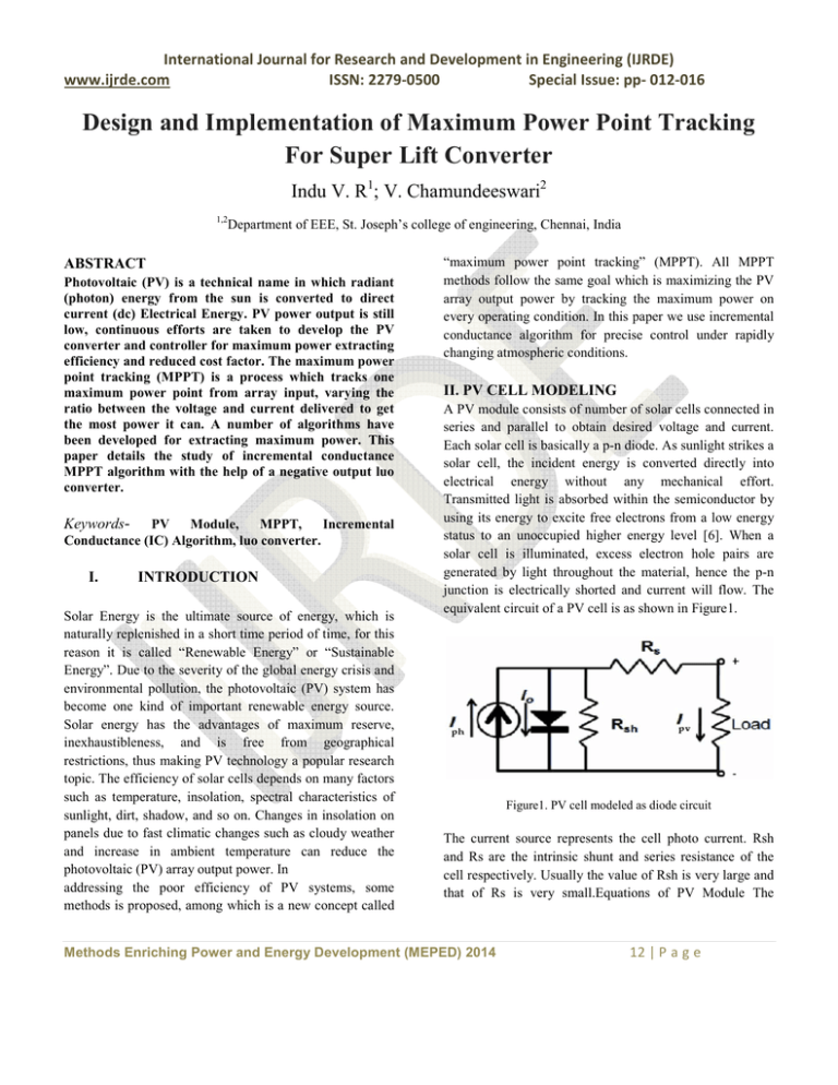
equivalent circuit of a PV cell is as shown in Figure1.
Figure1. PV cell modeled as diode circuit
The current source represents the cell photo current. Rsh
and Rs are the intrinsic shunt and series resistance of the
cell respectively. Usually the value of Rsh is very large and
that of Rs is very small.Equations of PV Module The
Methods Enriching Power and Energy Development (MEPED) 2014
12 | P a g e
International Journal for Research and Development in Engineering (IJRDE)
www.ijrde.com
ISSN: 2279-0500
Special Issue: pp- 012-016
photovoltaic module can be modeled mathematically as
given in equations shown below.
Module photo current:
Iph = [Isc + Ki (Tk - Tref)] * / 1000.
(1)
Module reverse saturation current:
Irs = Iscr/[exp( qV / N kAT ) .1]
(2)
The module saturation current Io varies with the cell
temperature, which is given by
Io = Irs(T/Tr )^3 exp((qEg/KA)*(1/Tr-1/T))
Figure 3 I-V characteristics of PV panel.
(3)
The current output of PV module is :
Ipv=Iph- Is*[exp{q(V pv +IpvRs)/Ns AKT}-1]
(4)
Where Vpv=Voc. Here we consider 36 series connected Pv
cells
Figure 4 P-V characteristic
III. MPPT
Figure 2 Simulink model
PV system naturally exhibits a nonlinear I-V and P-V
characteristics which vary with the radiant intensity and cell
temperature. The typical I-V and P-V characteristics of
solar cell are shown in figure 3& figure4.
MPPT algorithms are necessary in PV applications because
the MPP of a solar panel varies with the irradiation and
temperature, so the use of MPPT algorithms is required in
order to obtain the maximum power from a solar array.
Over the past decades many methods to find the MPP have
been developed and published. These techniques differ in
many aspects such as required sensors, complexity, cost,
range of effectiveness, convergence speed, correct tracking
when irradiation and or temperature change, hardware
needed for the implementation or popularity [1]. Among
these techniques, the P&O and the Incremental
Conductance algorithms are the most common. These
techniques have the advantage of an easy implementation.
Other techniques based on different principles are fuzzy
logic control, neural network, and fractional open circuit
voltage or short circuit current etc .Among different
Methods Enriching Power and Energy Development (MEPED) 2014
13 | P a g e
International Journal for Research and Development in Engineering (IJRDE)
www.ijrde.com
ISSN: 2279-0500
Special Issue: pp- 012-016
algorithms, Incremental Conductance method is used here.
In this method, the array terminal voltage is always adjusted
according to the MPP voltage. It is based on the
incremental and instantaneous conductance of the PV
module figure given below shows that the slope of the PV
array power curve is zero at the MPP, increasing on the left
of the MPP and decreasing on the right-hand side of the
MPPT .The basic equations of this method are as follows
dI/dV= - I/V, at MPP
(5)
dI/dV> − I/V, left of MPP
(6)
dI/dV< − I/V, right of MPP
(7)
Where, I and V are the PV array output current and voltage
respectively. The left-hand side of the equations represents
the Incremental conductance of the PV module, and the
right-hand side represents the instantaneous conductance.
From (5)–(7), it is obvious that when the ratio of change in
the output conductance is equal to the negative output
conductance, the solar array will operate at the MPP. In
other words, by comparing the conductance at each
sampling time, the MPPT will track the maximum power of
the PV module. The accuracy of this method is proven,
where it mentions that the Incremental conductance method
can track the true MPPs independent of PV array
characteristics. The efficiency was observed to be as much
as 98.2%, but it is some modifications and reformations
were proposed on this method so far, but since this method
inherently has a good efficiency, the aforementioned
amendments increase the complexity and cost of the system
and there was no remarkable change in system efficiency.
In this paper, control action is done using a microcontroller.
It generates pulse width modulation (PWM) waveform to
control the duty cycle of the converter switch according to
the Incremental conductance algorithm. Flow chart for the
incremental conductance is given below.
Figure 5. Incremental conductance algorithms
IV. CONVERTER
Luo converters were developed from the prototypes using
VL technique. These converters perform DC-DC voltage
increasing conversion with high power density, high
efficiency, and cheap topology in simple structure. They are
different from any other DC-DC step up converters and
possess many advantages including a high output voltage
with small ripples. Therefore, these converters are widely
used in computer peripheral equipment and industrial
applications, especially for high output voltage projects.
This paper introduces negative output super lift technique
that implements the output voltage increasing in stage by
stage along the geometric progression. Equation (8) shows
the input output relationship of luo converter
Vo = Vin/(1-k) (8)
The NOESLLC provides high voltage transfer gain using
Super-lift technique Its topology differs from the
conventional circuit as it uses additional capacitor in
parallel with the load boosting the output voltage. The
Methods Enriching Power and Energy Development (MEPED) 2014
14 | P a g e
International Journal for Research and Development in Engineering (IJRDE)
www.ijrde.com
ISSN: 2279-0500
Special Issue: pp- 012-016
linkage between input and output is alleviated which
degrades the output voltage. The above figure shows the
circuit diagram of NOESLLC. It consists of a power switch
MOSFET M1, Inductor L1, Resistor R1, Diodes D1, D2,
Capacitor C1, C2 and load resistance.
Figure 8 mode 2 representations
V. SIMULATION RESULTS
The simulation system consists of PV module; negative
output luo converter circuit and MPPT control block as
shown in the figure (9).
Figure 6 negative output luo converter
MODE1
When the switch is closed during the duty interval 0 to ∆T,
the supply voltage increases the current through the
inductor L1 and the capacitor C1 gets charged. The load
current is maintained constant by the discharge of the
capacitor C2 during this period
Figure 9 simulation system
Output power available at the output of the system without
MPPT is given in figure 10. By using incremental
conductance algorithm, PV panels working point is shifted
to the MPP and power output is increased.
Figure 7 mode 1 representation
MODE 2
During the duty interval ∆T to T the switch is closed where
the stored charges in the inductor supplies the load current
and the capacitor C1 and C2 produces the boosted voltage
across the load
Figure 10 PV output power without MPPT
Methods Enriching Power and Energy Development (MEPED) 2014
15 | P a g e
International Journal for Research and Development in Engineering (IJRDE)
www.ijrde.com
ISSN: 2279-0500
Special Issue: pp- 012-016
Electrical Energy in the 21st Century, July 20-24, 2008, Pittsburg,
USA.
Figure 11 Output power with MPPT.
VI. CONCLUSION
This paper presents the design and simulation for maximum
power point tracking (MPPT) for photovoltaic system,
which includes a high-efficiency luo converter with
incremental conductance algorithm. The converter can draw
maximum power from the PV panel for a given solar
insolation and temperature by adjusting the duty cycle of
the converter.
REFERENCES
[1] Azadeh Safari And Saadmekhilef, Member, IEEE, (2011)
“Simulation And Hardware Implementation Of Incremental
Conductance Mppt With Direct Control Method Using Cuk
Converter” IEEE Transactions On Industrial Electronics, Vol. 58,
No. 4, April 2011
[2] S. Nema, R.K.Nema, and G.Agnihotri, “Matlab / simulink
based study of photovoltaic cells / modules / array and their
experimental verification,” International Journal of Energy and
Environment, pp.487-500, Volume 1, Issue 3, 2010.
[3] N. Femia, D. Granozio, G. Petrone, G. Spagnuolo, andM.
Vitelli, “Predictive & adaptive MPPT perturb and observe
method,” IEEE Trans. Aerosp.Electron. Syst., vol. 43, no. 3, pp.
934–950, Jul. 2007.
[4] E. Koutroulis, K. Kalaitzakis, and N. C. Voulgaris,
“Development of a microcontroller-based, photovoltaic maximum
power point tracking controlsystem,” IEEE Trans. Power
Electron., vol. 16, no. 1, pp. 46–54,Jan. 2001.
[5] S. Jain and V. Agarwal, “A new algorithm for rapid tracking of
approximate maximum power point in photovoltaic systems,”
IEEE PowerElectron. Lett., vol. 2, no. 1, pp. 16–19, Mar. 2004.
[6] S.Chowdhury, S.P.Chowdhury, G.A.Taylor, and Y.H.Song,
“Mathematical Modeling and Performance Evaluation of a StandAlone Polycrystalline PV Plant with MPPT Facility,” IEEE Power
and Energy Society General Meeting -Conversion and Delivery of
Methods Enriching Power and Energy Development (MEPED) 2014
16 | P a g e

