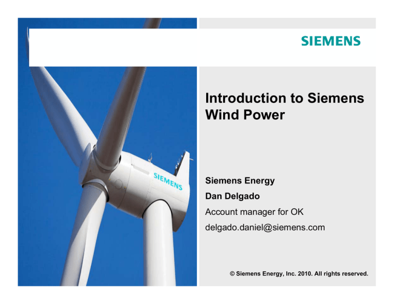
Introduction to Siemens
Wind Power
Siemens Energy
Dan Delgado
Account manager for OK
delgado.daniel@siemens.com
© Siemens Energy, Inc. 2010. All rights reserved.
Agenda
Company profile
Market overview
Product portfolio
Siemens scope of supply
Key differentiators
© Siemens Energy, Inc. 2010. All rights reserved.
Siemens AG divided into 3 global sectors
Healthcare
Energy
Industry
Sectors
Page 3
Divisions
Industry Automation
Osram
Drive Technologies
Industry Solutions
Building
Technologies
Mobility
Oil & Gas
Service Rotating
Equipment
Fossil Power
Generation
Renewable Energy
Power Transmission
Power Distribution
405,000 employees
190 countries
65,000 in U.S.A.
Annual Turnover (2009)
€77B
Siemens
Energy Sector
$25.7B or 34%
Siemens
Wind Power
$3B or ~4%
Imaging & IT
Workflow & Solutions
Diagnostics
© Siemens Energy, Inc. 2010. All rights reserved
Siemens Wind Power delivering strong, solid performance
Siemens Global Wind Power facts
Currently 6,200 employees (800 in 2004)
Deliveries: > 2260 MW in 2009 (600 MW in 2004)
Installed Base: > 8,700 turbines with > 11,000 MW capacity
Record wind turbine order backlog
Record order entry in FY 2009 and FY 2010
No. 1 in the global offshore market in 2009
No. 3 in the U.S. onshore market in 2009
Double digit growth in revenues, profit, installations and employees since
acquisition of Bonus
Page 4
© Siemens Energy, Inc. 2010. All rights reserved
Siemens is committed to the U.S. market
64,000 U.S. Siemens employees
9 headquarters located in the U.S.
Siemens Wind Power Headcount in the
Americas
Siemens Wind Power Installations in the
Americas (MW)
U.S.
1,400
1359
Canada
+120%
761
863
835
892
1162
573
791
387
3
2005
Page 5
60
2006
101
2007
2008
2009
2010
2006
2007
2008
198
2009
© Siemens Energy, Inc. 2010. All rights reserved
Recent Siemens Wind Power projects in the U.S.
On time, on budget and meeting performance
Tuolumne (Cascade)
96.6 MW
(2009)
Lower Snake River (PSE)
343 MW
Announced
Ridgewind (Ridgewind)
25 MW
(Under Construction)
Harvest Wind (Harvest Wind)
98.9 MW
(2009)
Windy Flats/Extension (Cascade)
202.4 MW / 59.8MW
(2009)
Top of the World (Duke)
101 MW
(Under Construction)
Biglow II & III (PGE)
149.5 MW & 174.8 MW
(2009/Under Construction)
Vansycle II (NextEra)
98.9 MW
(2009)
Cape Wind (EMI)
420 MW
Announced
Bison Wind (MP)
82 MW
(Under Construction)
Hatchet Ridge (Pattern)
101 MW
(2010)
Klondike III (Iberdrola)
2.3 MW
(2009)
OU Spirit (OGE/CPV)
101.2 MW
(2009)
Boulder Test (NREL)
2.3 MW
(2009)
N. Colorado (NextEra)
151.8 MW
(2009)
Elk City (NextEra)
98.9 MW
(2009)
South Trent (B&B)
101.2 MW
(2009)
Keenan II (CPV)
152 MW
(Under Construction)
Crossroads (OG&E)
227.5 MW
Announced
Papalote Creek II (E.ON)
200MW
(Under Construction)
Page 6
© Siemens Energy, Inc. 2010. All rights reserved
Continued growth in manufacturing, service and business
hubs to meet growth demand
Supply chain, R&D and sales presence in the
Americas
Siemens installations in the Americas (MW)
1300*
Ontario, Canada
(Business hub)
1090
Ontario, Canada
(Manufacturing
facility-planned)
Boston, MA
(Offshore)
Goldendale, WA
(Service)
Boulder, CO
(wind &
aerodynamics)
863
573
Ft. Madison, IA
(Blades)
Orlando, FL
(Americas
headquarters)
Hutchinson, KS
(Nacelles/ hub)
Mexico city, Mexico
(Local sales)
Sao Paulo, Brazil
(Business hub &
planned manufacturing)
Santiago de Chile
(Local sales)
Sales hubs
2006
2007
2008
2009
2010
More than 1,300 MW expected to be installed
in 2010
Houston, TX
(Americas
Service Center)
Supply chain
1162
Other sales
R&D
Service
Rapidly increasing Americas-based
employees and facilities for manufacturing
and service
More than 1,400* employees by end of 2010 in
different locations – Orlando, FL, Houston, TX,
Ft. Madison, IA, Ontario, Canada
*Estimated values
Page 7
© Siemens Energy, Inc. 2010. All rights reserved
Increasing capacity
Ft. Madison Plant Expansion
Warehousing
Manufacturing
Machining, rough & fine finish, and painting
Direct rail shipping
~500 employees/3 shifts
Manufactures B45 & B49 Wind
IntegralBlade®
New Nacelle Plant in Hutchinson, KS
Capacity of 1,500 MW per year
Creating more than 400 jobs in the
community
Initially assemble the 2.3 MW nacelle
First nacelle left the facility in December 2010
Page 8
© Siemens Energy, Inc. 2010. All rights reserved
Evolution of the product portfolio with over 30 years of
experience
Multi-Megawatt class
Megawatt class
Pitch technology with variable speed
SWT-2.3-82 VS and SWT-2.3-93: 2,335 WTG
SWT-2.3-101: 175 WTG
SWT-3.6-120
SWT-3.6-107: 220 WTG
SWT-3.6-120: 5 WTG
SWT-3.6-107
CombiStall technology
SWT-1.0-54: 356 WTG
SWT-1.3-62: 1,545 WTG
SWT-2.0-76: 165 WTG
SWT-2.3-82: 514 WTG
Kilowatt class
SWT-3.0-101 DD
SWT-2.3-101
SWT-2.3-93
SWT-2.3-82 VS
Stall technology
SWT-0.6-44: 1,316 WTG
< 600 kW: 2,330 WTG
SWT-2.3-82
SWT-2.0-76
Direct Drive Technology
Compact Direct Drive
SWT-3.0-101 DD
SWT-1.3-62
SWT-1.0-54
SWT-0.6-44
Former product portfolio
Existing product portfolio
Expansion to product portfolio - New Technology
Installed base worldwide: > 8,700 turbines with > 11,000 MW capacity
Page 9
© Siemens Energy, Inc. 2010. All rights reserved
Offering a product portfolio to meet the customer
requirements
Product portfolio
SWT-2.3-82VS
SWT-2.3-93
SWT-2.3-101
SWT-3.0-101 DD
Continuously monitoring market trends and needs for new product development
Page 10
© Siemens Energy, Inc. 2010. All rights reserved
Siemens offers turbine equipment for all wind conditions
SWT-3.0-101
IEC class: I A
Swept area: 8000m2
Annual output @ 9 m/s: 13.7 GWh
SWT-2.3-82VS
IEC class: I A
Swept area: 5,300 m²
Annual output @ 9 m/s: 9.2 GWh
SWT-2.3-93
IEC class: II A
Swept area: 6,800 m²
Annual output @ 8 m/s: 9.0 GWh
SWT-2.3-101
IEC class: II B
Swept area: 8,000 m²
Annual output @ 8 m/s: 10.1GWh
Page 11
© Siemens Energy, Inc. 2010. All rights reserved
The SWT-2.3-101 wind turbine optimizes your energy
yield in moderate wind conditions
Change in annual electricity production
Completes the SWT-2.3 family with
more performance in moderate wind
conditions
115%
SWT-2.3-101
110%
More output @ less noise
Same reliability as the SWT-2.3
family
105%
SWT-2.3-93
Pre-bent blades
100%
5
6
7
8
9
Wind speed [m/s]
10
Power Curves
Differences from the SWT2.3-93
Main difference is the Quantum blade
with advanced aerodynamics and load
reducing structural dynamics
New hub due to increase diameter
Same nacelle, power unit and towers (for
most of the sites)
2,500
SWT-2.3-101
Power [kW]
2,000
1,500
SWT-2.3-93
1,000
93
500
101
0
Page 12
0
5
10
15
20
Wind speed [m/s]
25
© Siemens Energy, Inc. 2010. All rights reserved
The SWT-2.3-101 wind turbine optimizes your energy yield
in moderate wind conditions
SWT-2.3-101 wind turbine generator
IEC Class:
Rotor diameter:
Blade length:
Swept area:
Hub height:
Power regulation:
Annual output at 8 m/s:
Blade weight:
Rotor weight:
Nacelle weight:
80 m tower weight (IEC IIB):
Experience Data
Prototype installed:
Serial production:
Total number installed:
Page 13
IIB
101 m
49 m
8,000 m2
80-100 m
pitch regulated, VS
10.1 GWh
10 t
62 t
82 t
170 t
2008
2010
200 operating
> 650 MW will be installed
before end of the year
© Siemens Energy, Inc. 2010. All rights reserved
SWT-3.0-101: Direct drive turbine with 101 m rotor
SWT-3.0-101 wind turbine generator
IEC class:
Rotor diameter:
Blade length:
Swept area:
Hub height:
Power regulation:
Annual output at 9 m/s:
Rotor weight:
Nacelle weight:
Nominal power:
IA
101 m
49 m
8,000 m2
Site specific
Pitch regulation, VS
13,700 MWh
60 t
73 t
3,000 kW
Proof of concept turbines:
Prototype installed:
Pilot series:
Serial production:
2008 + 2009
2009
2010
2011
Page 14
© Siemens Energy, Inc. 2010. All rights reserved
Newly introduced SWT-3.0-101 direct drive turbine
• Reduces complexity and increases
reliability and maintainability
• 50% fewer parts, half the parts of the
conventional geared turbine
• Simplified design for easier
transportation, erection and maintenance
• Compact and light weight
• Generator located at the front of the
nacelle, between the nacelle itself and
rotor hub; reduction of the equipment
inside the nacelle results in a shortened
4m length
Page 15
© Siemens Energy, Inc. 2010. All rights reserved
Our unique blade manufacturing technology
avoids glue joint potential blade weaknesses
IntegralBlade® technology is a closed process
invented by Siemens.
Manufactured in one piece
Superior strength and resilience due to an
integrated structure
No glue joints which reduce the risk for adverse
effects of cracking and water ingress
Designed for excellent power and noise
performance due to superior aerodynamics, profile
accuracy and damping
Page 16
© Siemens Energy, Inc. 2010. All rights reserved
Siemens’ long experience with condition monitoring can
optimize fleet performance and save large costs
The TCM® system allows for the
continuous online vibration monitoring
of the wind turbine with sensors and
allows for the assessment of:
Main bearing
Gearbox
Generator
10 years of experience with thousands
of turbines allows for precise
diagnostics and preventive service
planning.
The system is certified by Germanischer
Lloyd
Page 17
© Siemens Energy, Inc. 2010. All rights reserved
Robust design features contribute to longer lifetime and
higher reliability
Selected high quality features
Lubrication
System
Continuously fed automatic lubrication system
with oil temperature control
In-line and off-line oil filters
New oil from the supplier is pre-filtered
Yaw
System
Reduced loads with more motors and gradual
ramp-up through a frequency converter
Hardened yaw ring and gears for maintenancefree operations
Steel Canopy
Very robust design and low material
flammability
Extra lightning protection, functioning as
Faraday cage
Designed to withstand turbulence class A winds
Page 18
© Siemens Energy, Inc. 2010. All rights reserved
Robust design features contribute to longer lifetime and
higher reliability (cont’d)
Selected high quality features
Cooling
System
Fully closed cabinet solely cooled by means
of heat exchangers provides perfect
isolation
Dehumidifiers in offshore wind turbines
Water cooling of frequency converter
Lightning
Protection
Blades equipped with lightning receptors
and a flexible insulated metal wire
Full metal design
Transformer outside nacelle reduces fire risk
Page 19
© Siemens Energy, Inc. 2010. All rights reserved
Siemens NetConverter® responds to grid codes with
maximum flexibility and top performance
Siemens NetConverter® Capabilities
Operation range
Accommodate a wide range of
frequency and voltage
disturbances
Power quality
Minimum harmonic content
and flicker emission
Low Voltage Ride Through
Advanced LVRT capabilities to
meet the most demanding grid
codes
Page 20
Active power control
Multiple options to respond to
under-frequency and overfrequency events
Voltage regulation
Best-in-class voltage regulation
capabilities, even with no wind
© Siemens Energy, Inc. 2010. All rights reserved
Capacity Factor Comparisons of 80 to ~100M towers
Wind speed=8.85m/s
SWT 2.3-101
Net AEP (GWh)
8,57%
Capacity Factor (%)
4,29%
54,3
10,94
50,0
10,08
80m
99.5m
• Assumption: 95% Availability, 91.18% Park Efficiency
• P50
Page 21
© Siemens Energy, Inc. 2010. All rights reserved
Comprehensive service solutions
What makes Siemens’ service solutions unique?
OEM knowledge and engineering support
Skilled and experienced personnel available 24/7
Comprehensive portfolio of service contracts
24/7 remote monitoring capability
Technical field assistance to support scheduled and
unscheduled outages
Access to Siemens’ global logistics network with
day-to-day management and control of inventory
results in reduced lead-time for spare parts
In-house training facility for customers
Page 22
© Siemens Energy, Inc. 2010. All rights reserved
Exceptional innovation
Hywind
Page 23
Cooperation on technology with Statoil Hydro to develop
World's first floating off-shore installation
In 2009 Siemens installed the first turbine in Norway at a water
depth of about 220 meters
Floating offshore turbines could be installed at sites with greater
water depths
Reduced visual impact and increased power production due to
strong and stable wind conditions
© Siemens Energy, Inc. 2010. All rights reserved
Siemens Boulder Wind R&D Team
Goal - Supporting Siemens Wind Power to lower cost of electricity
by increasing energy production, lowering turbine cost and
improving reliability
Siemens Wind R&D Boulder is focused on the following technology areas:
Loads – Reduce mechanical loading per unit of energy = lighter blades and structures =
cost savings = Lower COE
Aerodynamics – Improve efficiency = higher capacity factors = Lower COE
Controls- Improve energy output and lower loading = Lower COE
Wind Power Meteorology –optimize Turbine design and operation of wind farms = Lower
COE
Product Integrity - Support prototype and turbine testing in the Americas
Page 24
© Siemens Energy, Inc. 2010. All rights reserved
Boulder CRADA, Introduction
•
Cooperative Research And Development Agreement between
Dept. of Energy, DOE/ National
Renewable Energy Lab, NREL and Siemens Wind Power
•
•
A SWT-2.3-101 wind turbine is erected at NWTC, Boulder
Budget: DOE/NREL $5M
Siemens $9M
•
Time plan: Jan 2009- Jan 2012
• In a close cooperation between
NREL and Siemens numerous test
campaigns and data analysis will
be performed
Commissioning Ceremony, October 19th, 2009
Page 25
© Siemens Energy, Inc. 2010. All rights reserved
Boulder CRADA
Technology Development Project
Objectives
The primary objective is to gain
detailed knowledge of
performance, aerodynamics,
noise emission and structural
characteristics of the SWT-2.3101 wind turbine being operated at
a severe wind condition site with
strong wind shear and high
turbulence intensity.
New measurement technologies
The measured data will serve as a
unique and valuable verification
and validation data set for
improvement and further
development of wind turbine design
codes used in Siemens Wind
Power
The test campaign is part of a
Cooperative Research and
Development Agreement (CRADA)
between Siemens Wind Power A/S
and National Renewable Energy
Lab, NREL in Boulder, Colorado
The wind turbine being tested is
the Siemens SWT-2.3-101, which
is rated at 2.3 MW and has hub
height of 80 m and a rotor diameter
of 101 m
The turbine was erected October
2009 and tests are planned to run
until January 2012.
Page 26
Tests
Inflow
Power performance
Power quality
Noise emission
Loads
Blade torsion and modal test
Reliability under severe conditions
Full scale rotor aerodynamics
Enhanced performance and load
reduction
A 135 m met tower is located 200m
upstream of the turbine. The tower
is instrumented with six sonics
anemometers and four cup
anemometers and vanes
A Windcube LIDAR is located 280
m upstream of the turbine. The
LIDAR can measure inflow wind at
several heights between 10 and
250 m
Flow Visualization
Tufts on the suction side of the root section for
visualizing the surface flow. Here with two rows of
VGs. The separated region is clearly seen.
Investigation of Vortex Generators on the outer part of the
blades using oil flow visualization. The flow is on the
suction side at rotor radius and centered at about ~ 44 m.
The VGs are removed between the two dashed lines.
© Siemens Energy, Inc. 2010. All rights reserved
Questions?
© Siemens Energy, Inc. 2010. All rights reserved.


