Product Overview
Triangle BioSystems, Int’l.
16 Channel Tethered Headstages
Gain 2, 20 and 100
Headstage Features
• Custom VLSI circuit provides
small size & reduced weight
• Weight < 0.75 grams
• 17 channels total (16 data channels
and 1 reference channel)
• Available with gain of 2, 20, 100
• Unity gain ground buffer output
• Selectable bandpass filtering per
channel
• ± 1.65V/±2.5V operation
• Gain 2 size: 3 x 8 x 15 mm
Gain 20 & 100 size: 3 x 9 x 20 mm
Gain 2
Gain 20, 100
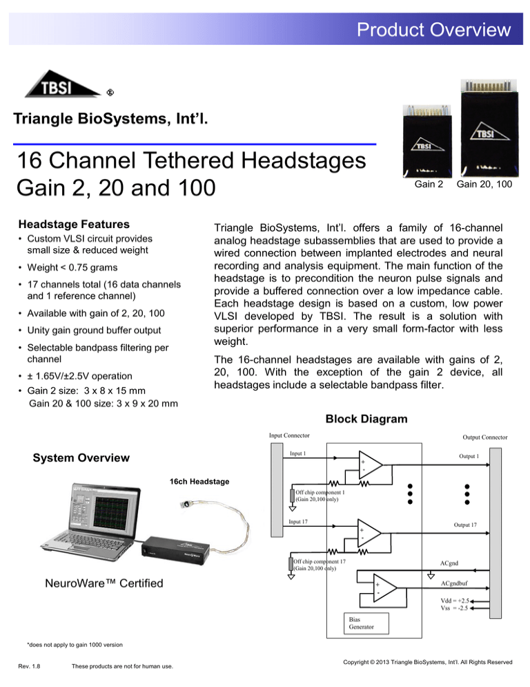
Triangle BioSystems, Int’l. offers a family of 16-channel
analog headstage subassemblies that are used to provide a
wired connection between implanted electrodes and neural
recording and analysis equipment. The main function of the
headstage is to precondition the neuron pulse signals and
provide a buffered connection over a low impedance cable.
Each headstage design is based on a custom, low power
VLSI developed by TBSI. The result is a solution with
superior performance in a very small form-factor with less
weight.
The 16-channel headstages are available with gains of 2,
20, 100. With the exception of the gain 2 device, all
headstages include a selectable bandpass filter.
Block Diagram
Input Connector
Output Connector
Input 1
System Overview
Output 1
+
-
16ch Headstage
Off chip component 1
(Gain 20,100 only)
Input 17
Output 17
+
-
Off chip component 17
(Gain 20,100 only)
ACgnd
NeuroWare™ Certified
+
-
ACgndbuf
Vdd = +2.5
Vss = -2.5
Bias
Generator
*does not apply to gain 1000 version
Rev. 1.8
These products are not for human use.
Copyright © 2013 Triangle BioSystems, Int’l. All Rights Reserved
Headstage Specifications
Electrical
Parameter
Min
Typ
Max
3.0
5.6
4.5
6.8
3.3
6.1
5
7.5
3.6
6.7
5.5
8.5
Volts
mA
Volts
mA
3.3V Bipolar power supply (± 1.65V)
0
1.8
.8
Volts
Volts
Volts
mVolts
For 5V Bipolar power supply
For 3.3V Bipolar power supply
For bipolar power supplies only
For bipolar power supplies only
Factory selectable gain
Factory selectable gain
Factory selectable gain
DC coupled
-3dB input signal level BW
-3dB input signal level BW
At 1kHz
At 1kHz
for DC - 10khz frequency with all inputs grounded
@ 5kHz and 1V p-p input
@ 5 kHz input
With 1V step input
Units
Notes
Power Supply
±1.65 volt supply
Average Icc
±2.5 volt supply
Average Icc
5V Bipolar power supply (± 2.5V)
Analog Channel
Input voltage range (±2.5V)
Input voltage range (±1.65V)
Common mode center
DC Offset
Voltage Gain 2
Voltage Gain 20
Voltage Gain 100
G2 BW @ ±2.5V
G20 BW @ ±2.5V
G100 BW @ ±2.5V
Input impedance
Output impedance
Input referred noise
THD
Phase Delay
Settling Time
-1.2
-.6
0
0
2
20
100
-10
1.9
19.8
95
.8
.8
10
2.1
20.2
105
250
150
22
50
158
5.1
-63
30
5.5
kHz
kHz
kHz
Mohms
ohms
µVrms
dB
uSecs
uSecs
Mechanical Specs
Gain 2 (H x L x W)
Gain 20 & Gain 100
Weight Gain 2
Weight Gain 20
3
3
8
9
15
20
.4
.7
mm
mm
grams
grams
Edge to Edge of connector pins H x W x L
Edge to Edge of connector pins H x W x L
uA
C
Included inside headstage
Miscellaneous
Reference Bias Current
Junction Temperature
-40
78
25
100
Connectors
Mate logo to logo for correct connector orientation.
Looking At Input Electrode Connector (Omnetics A8783-001):
NC
PCB
NC
NC CH17/
ACGnd
Custom VLSI ASIC
CH1
CH2
CH9 CH10
CH3
CH4
CH5
CH6
CH11 CH12 CH13 CH14
CH7
CH8
NC
NC
CH15 CH16 ACGnd NC
Guide Pin
PCB
Looking At Output Connector (Omnetics A8811):
NC
PCB
Vdd
ACGND GND
BUF
CH16 CH15
nVdd
CH8
CH14
CH13
CH7
CH6
CH12 CH11
CH5
CH4
CH10
CH9
CH17
CH3
CH2
CH1
NC
ACGND
Guide Pin Hole
PCB
Ordering Information
Part No.
Compact Size
2224 Page Rd.
Suite 108
Durham, NC 27703
P 919 361 2663
F 919 544 3061
www.trianglebiosystems.com
Rev. 1.8
Gain
BP Filter
Neuro16G2
Gain 2
No
Neuro16BPG20
Gain 20
Yes
Neuro16BPG100
Gain 100
Yes
Copyright © 2013 Triangle BioSystems, Int’l. All Rights Reserved
Application Notes
Available Grounding and Referencing
Connections for T16G2,20,100 Headstage:
ACGND: Connect your animal ground to
ACGND (see pinout diagram on pg2) of the
headstage. This is typically connected to earth
or system ground (which is 0V potential) of the
recording system.
CH17: This is an extra recording channel that
can be used as a common mode reference
signal for external preamplifiers. This common
mode reference channel is useful for removing
animal movement artifacts or any other
common mode noise found at the headstage
input pins.
ACGNDBUF: With ACGND as the positive
input, this pin uses a unity gain source follower
to provide another common mode reference
option for the preamplifier. NOTE: The
ACGNDBUF is DC coupled with unity gain and
does not have the same bandpass filter
characteristics as channels 1-17. Therefore
the common mode noise rejection when using
ACGNDBUF may not be as effective as
channels 1-17.
Common Mode
Reference Jumper
CH4
CH5
CH6
6
5
4
3
23
13
22
12
21
Gain 20
1
11
20
CH15
24
14
2
CH14
25
15
CH13
CH9
26
ACGND (Pins 11 thru 17)
16
CH12
17
CH11
18
CH8
CH3
7
10
-3V
19
CH16
CH2
8
Gain 2
CH7
CH1
9
CH10
CH17
+3V
Front View
Rear View
Gain 100
* 16ch T-series recording unit is
exclusively powered via USB
2224 Page Rd.
Suite 108
Durham, NC 27703
P 919 361 2663
F 919 544 3061
www.trianglebiosystems.com
Rev. 1.8
Copyright © 2013 Triangle BioSystems, Int’l. All Rights Reserved


