ISSN: 2278 – 1323
International Journal of Advanced Research in Computer Engineering & Technology (IJARCET)
Volume 5, Issue 6, June 2016
Review Performance of Transmission Lines using Static Synchronous Series
Compensator
Hitendra kumar1
Amit Goswami2
DIMAT Raipur
CSVTU Bhilai Chhattisgrah India
Abstract- The power system industry is a field
where there are constant changes occurs.
Economic and environmental pressures force
electric companies to enhance the power
transfer capability of the existing transmission
lines instead of constructing new ones. Besides
allowing a better utilization of existing power
systems capacity, FACTS controllers can control
network parameters, such as magnitude of
sending-end and receiving-end voltage, and
active-reactive power, to improve both the
transient stability performance of the system. In
thesis work describe the Static synchronous
series compensator device, that controls the
power flow of the transmission line during sever
disturbances. Basics of Static synchronous series
compensator is that it does not contains bulky
component like reactor and inductor so this
device is more economical compare to
conventional devices. And characteristic of
Static synchronous series compensator is that
injects or absorbs the reactance in the system
and control the power. In thesis work two
machine bus system with and without discrete
PI controller and SSSC converter simulated in
MATLAB .Simulation result obtained for
selected Bus-3 in two machine power system
shows that with SSSC the active-reactive
powers, voltage - current compensation and
damping out oscillation appropriately. In short
in the power system when any disturbance
occurs at that time if Static synchronous series
compensator controller is connected at there so
any disturbance occurs on the system may reach
steady state condition very quick.
inductor to meet the requirements of the
transmission system. When the structure of the
transmission network is considered, power
flow imbalance problems arise. Inadvertent
interchange occurs when the power system tie
line becomes corrupted. This is because of
unexpected change in load on a distribution
feeder due to which the demand for power on
that feeder increases or decreases. The
generators are to be turned on or off to
compensate for this change in load. If the
generators are not activated very quickly,
voltage sags or surges can occur. In such
cases, controlled series compensation helps
effectively.
Here in this paper a new simple concept is
introduced with simultaneous operation of two
machine system with SSSC converter. The
SSSC is connected at bus-3 of the transmission
line. The two-machine power system is
simulated using MATLAB and the effect of
with and without SSSC on system and in fault
condition are simulated.
1. INTRODUCTION
Series compensation is a means of controlling
the power transmitted across transmission
lines by altering or changing the characteristic
impedance of the line. The power flow
problem may be related to the length of the
transmission line. The transmission line may
be compensated by a fixed capacitor or
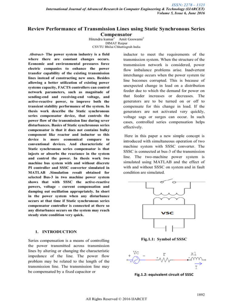
Fig.1.1: Symbol of SSSC
Fig.1.2: equivalent circuit of SSSC
1892
All Rights Reserved © 2016 IJARCET
ISSN: 2278 – 1323
International Journal of Advanced Research in Computer Engineering & Technology (IJARCET)
Volume 5, Issue 6, June 2016
The static sysnchronous series compensator
(SSSC) is a series device of the Flexible AC
Transmission Systems (FACTS) family using
power electronics to control power flow and
improve transient stability on power grids. In
place of using capacitor and reactor banks, a
SSSC use self-commutated voltage-source
switching converters to synthesize a threephase voltage inquadrature with the line
current. The main interest is to use the SSSC
for controlling flow of power (active and/or
reactive) in transmission lines, whereas the
SSSC is mainly recommended for damping
electromechanical oscillations. Thus, the SSSC
control system may be made by a
compensation control loop, to accomplish its
steady-state function, and by a fast response
control, to act during electromechanical
transients.[9][11]
Fig.1.3: Phasor diagram
The system investigated for this paper is base
on the First IEEE Benchmark Model[17] with
some modifications, as depicted in Fig.3. The
generator is connected to an infinite bus
through a radial series compensated line. The
generator is 50MVA and delivers 0.9 p.u.
power to the transmission system. The
excitation system is simplified with constant
excitation voltage. The total line compensation
degree is set to 50%. The SSSC is added
downstream from the step-up transformer to
replace a portion of the line compensation. The
rotor shaft model is composed of six masses,
which are the high-pressure (HP) turbine, the
intermediate-pressure (IP) turbine, the two
separate low-pressure turbines (LPA and
LPB), the generator and the rotating exciter.
The detailed electrical and mechanical data are
provided in [17].
1.1 SSSC CONTROLSYSTEM
The Static Synchronous Series Compensator
(SSSC) is aseries device of the Flexible AC
Transmission Systems(FACTS) family using
power electronics to control power flow and
improve power oscillation damping on power
grids [1]. The SSSC is injects a voltage Vs in
series with the transmission line where it is
connected. Figure (3.1) shows single line
diagram of SSSC transmission system and its
control structure. As the SSSC does not use
any active power source, the injected voltage
must stay in quadrature with line current. By
varying the magnitude of the injected voltage
Vq in quadrature with current, the SSSC
performs the function like a variable reactance
compensator either capacitive or inductive.
The variation in injected voltage is performed
by means of a Voltage-Sourced Converter
(VSC) that is connected on the secondary side
of a coupling transformer. The VoltageSourced Converter (VSC) uses forced
commutated power electronic devices (GTOs
or IGBTs) to synthesize a voltage Vconv from
a DC voltage. A capacitor connected on the
DC side of the VSC acts as a DC voltage
source. In this a small active power drawn
from the line to keep the capacitor charged and
provide to transformer, so that the injected
voltage Vs is practically 90 degrees out of
phase with current I. the control system block
diagram Vd conv and Vq conv designated the
components of converter voltage Vconv which
are respectively in phase and in quadrature
with current. VSC using GTO-based squarewave inverters and special interconnection
transformers. In this system typically four
three-level inverters are used to build a 48-step
voltage waveform. Special interconnection
transformers technique are used to neutralize
harmonics contained in the square waves
generated by individual inverters. In this
Voltage- Sourced Converter (VSC), the
fundamental component of
voltage Vconv is proportional to the voltage
Vdc . This type of inverter uses Pulse-Width
Modulation (PWM) technique to synthesize a
sinusoidal waveform from a DC voltage with a
1893
All Rights Reserved © 2016 IJARCET
ISSN: 2278 – 1323
International Journal of Advanced Research in Computer Engineering & Technology (IJARCET)
Volume 5, Issue 6, June 2016
typical chopping frequency of a few kilohertz.
Harmonics are eliminating by connecting
filters at the AC side of the VSC. This type of
VSC uses a fixed type of DC voltage Vdc .
Voltage Vconv is varied by changing the
modulation index of the PWM modulator
Figure 1.3 Control System Block Diagram
Diagram of a SSSC..
A phase-locked loop (PLL) which
synchronizes on the positive-sequence
component of the current I. The output of the
PLL (angle Θ=ωt) is used to compute the
direct-axis and quadrature-axis components of
the AC three-phase voltages and currents
(labeled as Vd, Vq or Id, Iq on the
diagram).Measurement systems measuring the
q components of AC positive-sequence of
voltages V1 and V2 (V1q and V2q) as well as
the DC voltage Vdc. AC and DC voltage
regulators which compute the two components
of the converter voltage (Vd_conv and
Vq_conv) required obtaining the desired DC
voltage (Vdcref) and the injected voltage
(Vqref). The Vq voltage regulator is assisted
by a feed forward type regulator which
predicts the Vconv voltage from the Id current
measurement
.2 TWO MACHINE MODEL OF SSSC
The two machine model has generation
substations and one load centre. The
generation substation (G 1) has a rating of
2100 MV A and the other substation (G2)
which has a rating of 1400 MV A. The
transmission lines are used to connect the load
and the machines. Simulation is performed
under single phase fault in the transmission
line applied across the selected bus .. The
SSSC is situated near the bus B2 which is in
series with the transmission line as shown in
the beloved figure. In the simulation the power
flow control is done by utilising the SSSC in
the transmission systems. The power system
consists of bus 2.An output comparative
analysis is done with and without SSSC in the
two machine system.SSSC The two machine
systems with three buses are connected using
the transmission lines without SSSC. Here the
transient mode is created by single phase fault
at the selected bus using the transition time
which is set as follows [5 6].The simulation
results shows the system performances like
voltage, line power, active power and reactive
power. Lines L I, L2 separately.
Figure2.1:Simulink diagram representation of
proposed work.
3 RESULTS AND DISCUSSIONS
The Power regulation using a Static
Synchronous Series compensator (SSSC) has
been successfully implemented in the
Simulink. This section deploys the results
1894
All Rights Reserved © 2016 IJARCET
ISSN: 2278 – 1323
International Journal of Advanced Research in Computer Engineering & Technology (IJARCET)
Volume 5, Issue 6, June 2016
obtained and steady state and dynamic
performance analysis of results obtained. For
the comparative analysis a three phase fault is
generated on times 1.33 and 1.5 sec using
three phase fault generator. Let us first take the
three phase transmission line system without
SSSC. Figure (5.1) illustrates, the power
obtained at bus B2 without SSSC. Figure (5.2)
shows the power obtained at all the buses B1,
B2, B3 and B4 without SSSC.
Fig.3.1 :Power obtained at all the buses B1,
B2, B3 and B4 without SSSC
REFERENCES
[1] N. G. Hingorani and L. Gyugyi ,
“Understanding FACTS concepts and
Technology of flexible AC transmission
systems”, New York. IEEE Press, 2000.
[2] E.Acha., H Ambriz-Perez and Fuerte-Esquivel
“Advanced SVC Models for NewtonRaphson Load Flow and Newton Optimal
Power Flow Studies”, IEEE Transactions on
Power Systems, Vol. 15(1), p.129-136, 2000.
[3] L Cai “ Robust Co-ordinated Control of
FACTS Devices in Large Power Systems” a
PhD Thesis, University of Duisburg,
Germany, published by Logos Verlag Berlin,
2004.
[4] T. Orfanogianni and R. Bacher. “Steady-state
optimization in power systems with series
FACTS devices”, IEEE Transactions on
Power Systems, Vol. 18(1), pp.19–26, 2003.
[5] B.H. Kim and R. Baldick. “A comparison of
distributed optimal power flow algorithms”,
IEEE Transactions on Power Systems, Vol.
15(2), pp. 599–604, 2000.
[6] Ishwar Lal Yadav Stability Enhancement for
Transmission Lines using Static Synchronous
Series Compensator International Journal of
Engineering Research & Technology (IJERT)
ISSN:2278-0181IJERTV4IS020811 Vol. 4
Issue 02, February-2015
4 CONCLUSION
The advancement in the technology like
homeequipments and plant equipments,
demands for precession and highly regulation
in the received power from energy generator
through the lines, because in current scenario
the equipments are very much sensitive to
supply power regulation. Any kind of
fluctuation either damage the costly equipment
or may harm full for further used equipments.
In this paper used algorithm shows an efficient
solution of this problem. In this paper, a Static
Synchronous Series compensator (SSSC) is
has been investigated to analyze the effect of
this device in controlling active and reactive
powers as well as damping power system
oscillations in transient mode. The SSSC setup
with a source of energy in the DC link can
supply or absorb the reactive and active power
to or from the line. Complete Simulations have
been
done
in
MATLAB/SIMULINK
environment.
1895
All Rights Reserved © 2016 IJARCET

