High dV/dt immunity MOS controlled thyristor using a
advertisement
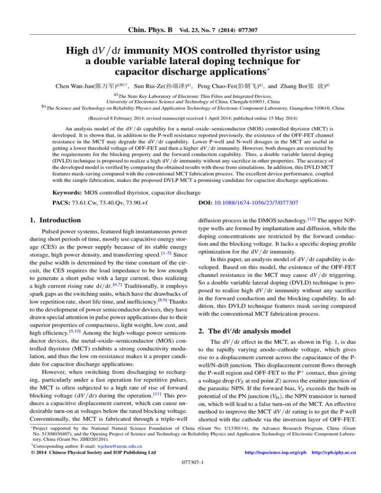
Chin. Phys. B Vol. 23, No. 7 (2014) 077307 High dV /dt immunity MOS controlled thyristor using a double variable lateral doping technique for capacitor discharge applications∗ Chen Wan-Jun(陈万军)a)b)† , Sun Rui-Ze(孙瑞泽)a) , Peng Chao-Fei(彭朝飞)a) , and Zhang Bo(张 波)a) a) The State Key Laboratory of Electronic Thin Films and Integrated Devices, University of Electronics Science and Technology of China, Chengdu 610051, China b) The Science and Technology on Reliability Physics and Application Technology of Electronic Component Laboratory, Guangzhou 510610, China (Received 8 February 2014; revised manuscript received 1 April 2014; published online 15 May 2014) An analysis model of the dV /dt capability for a metal–oxide–semiconductor (MOS) controlled thyristor (MCT) is developed. It is shown that, in addition to the P-well resistance reported previously, the existence of the OFF-FET channel resistance in the MCT may degrade the dV /dt capability. Lower P-well and N-well dosages in the MCT are useful in getting a lower threshold voltage of OFF-FET and then a higher dV /dt immunity. However, both dosages are restricted by the requirements for the blocking property and the forward conduction capability. Thus, a double variable lateral doping (DVLD) technique is proposed to realize a high dV /dt immunity without any sacrifice in other properties. The accuracy of the developed model is verified by comparing the obtained results with those from simulations. In addition, this DVLD MCT features mask-saving compared with the conventional MCT fabrication process. The excellent device performance, coupled with the simple fabrication, makes the proposed DVLP MCT a promising candidate for capacitor discharge applications. Keywords: MOS controlled thyristor, capacitor discharge PACS: 73.61.Cw, 73.40.Qv, 73.90.+f DOI: 10.1088/1674-1056/23/7/077307 1. Introduction Pulsed power systems, featured high instantaneous power during short periods of time, mostly use capacitive energy storage (CES) as the power supply because of its stable energy storage, high power density, and transferring speed. [1–5] Since the pulse width is determined by the time constant of the circuit, the CES requires the load impedance to be low enough to generate a short pulse with a large current, thus realizing a high current rising rate di/dt. [6,7] Traditionally, it employs spark gaps as the switching units, which have the drawbacks of low repetition rate, short life time, and inefficiency. [8,9] Thanks to the development of power semiconductor devices, they have drawn special attention in pulse power applications due to their superior properties of compactness, light weight, low cost, and high efficiency. [9,10] Among the high-voltage power semiconductor devices, the metal–oxide–semiconductor (MOS) controlled thyristor (MCT) exhibits a strong conductivity modulation, and thus the low on-resistance makes it a proper candidate for capacitor discharge applications. However, when switching from discharging to recharging, particularly under a fast operation for repetitive pulses, the MCT is often subjected to a high rate of rise of forward blocking voltage (dV /dt) during the operation. [11] This produces a capacitive displacement current, which can cause undesirable turn-on at voltages below the rated blocking voltage. Conventionally, the MCT is fabricated through a triple-well diffusion process in the DMOS technology. [12] The upper N/Ptype wells are formed by implantation and diffusion, while the doping concentrations are restricted by the forward conduction and the blocking voltage. It lacks a specific doping profile optimization for the dV /dt immunity. In this paper, an analysis model of dV /dt capability is developed. Based on this model, the existence of the OFF-FET channel resistance in the MCT may cause dV /dt triggering. So a double variable lateral doping (DVLD) technique is proposed to realize high dV /dt immunity without any sacrifice in the forward conduction and the blocking capability. In addition, this DVLD technique features mask saving compared with the conventional MCT fabrication process. 2. The dV /dt analysis model The dV /dt effect in the MCT, as shown in Fig. 1, is due to the rapidly varying anode–cathode voltage, which gives rise to a displacement current across the capacitance of the Pwell/N-drift junction. This displacement current flows through the P-well region and OFF-FET to the P+ contact, thus giving a voltage drop (VZ at red point Z) across the emitter junction of the parasitic NPN. If the forward bias, VZ exceeds the built-in potential of the PN junction (Vbi ), the NPN transistor is turned on, which will lead to a false turn-on of the MCT. An effective method to improve the MCT dV /dt rating is to get the P well shorted with the cathode via the inversion layer of OFF-FET. ∗ Project supported by the National Natural Science Foundation of China (Grant No. U1330114), the Advance Research Program, China (Grant No. 51308030407), and the Opening Project of Science and Technology on Reliability Physics and Application Technology of Electronic Component Laboratory, China (Grant No. ZHD201201). † Corresponding author. E-mail: wjchen@uestc.edu.cn © 2014 Chinese Physical Society and IOP Publishing Ltd http://iopscience.iop.org/cpb http://cpb.iphy.ac.cn 077307-1 Chin. Phys. B Vol. 23, No. 7 (2014) 077307 cathode (emitter) BPSG poly gate x cathode LN P+ LP P+ LG BPSG poly gate OFFFET N -well gate depletion region boundary NPN OFFFET Pwell ONFET displacement current point Z Ndrift PNP W P+ anode (collector) V2 anode dV/dt V1 Fig. 1. (color online) (a) A diagram of dV /dt triggering in MCT, and (b) equivalent circuit of the MCT. Obviously, the dV /dt immunity is influenced in principle by the intensity of the inversion layer of the OFF-FET channel. The dV /dt capability can be analyzed in capacitor discharge by the following analysis. The VZ is the voltage drop of the displacement current along the total specific resistance Rtotal of the P well and the OFF-FET channel and is given by VZ = JC Rtotal . (1) The displacement current density JC is amplified by a factor of (1 − αPNP )−1 as the base current for the parasitic PNP transistor and is given by JC = CD dV , (1 − αPNP ) dt (2) where CD is the depletion capacitance of the P-well/N-well junction. The total specific resistance consists of the P-well resistance and the OFF-FET channel resistance, and is given by Z Rtotal = ρxdx = Z LP−well 0 ρxdx + Rch , (3) where LP−well , ρ, and Rch are the half P-well length, the square resistance of the P well, and the specific resistance of the OFFFET channel, respectively. Thus, VZ is expressed as VZ = 0 JC ρxdx + JC Rch 2 CD ρLP−well dV CD Rch dV + , 2 (1 − αPNP ) dt 1 − αPNP dt Ltox = , Zµp εox |VG −VTH | = Rch Z LP−well layer, the gate oxide thickness, and the dielectric constant, respectively. From Eq. (5), it can be seen that the difference between the gate bias (VG ) and the threshold voltage of OFFFET (VTH ) strongly determines Rch . On the other hand, VTH is influenced by the N-well concentration ND at the OFF-FET region, which is realized by the compensation between P-well and N-well dosages. Their relationship is given by VTH = ψMS − 1 tox tox Qox − 2 (−qεs ND ψFn ) 2 + 2ψFn , (6) εox εox where ψMS is the difference of the work function between the gate material and silicon, ψFn is the flat band voltage of the n-type silicon, Qox is the fixed charge in the gate oxide layer, and ε s is the dielectric constant of silicon. The dV /dt triggering occurs when VZ exceeds Vbi . Thus, the dV /dt capability is given as s dV 2Vbi 2VA = (1 − αPNP ) , (7) 2 dt ρLP−well + 2Rch qND εs where VA is the applied anode voltage. From Eq. (7), 2 ρLP−well and Rch are two key physical device parameters 2 that affect dV /dt. Obviously, ρLP−well relies on the P-well impurity dosage QP and the profile; Rch is mainly determined by the N-well impurity dosage QN and VG . The typical P-well and N-well concentrations are 5×1016 cm−3 and 2 2×1018 cm−3 , respectively, leading to ρLP−well = 7.7 µΩ·cm2 2 (4) (5) where Z, L, µ p , tox , ε ox are the OFF-FET channel width, the OFF-FET channel length, the hole mobility in the inversion and Rch = 63.3|V µΩ·V·cm . The term Rch varies as |VG −VTH | G −VTH | 2 changes. If the relationship 2Rch ρLP−well is satisfied, then the term of Rch can be omitted. The dV /dt capability will rely on the P-well width and the doping profile, which is rep2 resented as ρLP−well . This situation has been discussed clearly [11] before and will not be discussed here. In this paper, we 077307-2 Chin. Phys. B Vol. 23, No. 7 (2014) 077307 2 concentrate on the situation of ρLP−well 2Rch , which is usually caused by undesirable high |VTH |. Substituting Eqs. (5) and (6) into Eq. (7) provides a simplified expression 1 s 2 ε Zµ V A − BN ox ni bi D dV 2VA (1 − αPNP ), (8) dt = KG tox Lch qND ε dosage in the P well for blocking. Thus, the DVLD technique can realize a desired doping profile for the enhancement in the di/dt and dV /dt capability simultaneously. It is economically better because of the less high temperature process and one mask being saved. where tox A = ψMS − Qox + 2ψFn , εox 1 2tox (−qεs ψFn ) 2 . B= εox Nwell (9) Pwell FLR mask for VLD Pwell Pwell 2nd diffusion poly gate Nwell mask for VLD Nwell Nwell P+ contact Ndrift process continues ... (a) VLDPwell mask (b) VLDNwell mask poly gate poly gate Nwell Pwell Pwell Ndrift Ndrift implanted window for positive PR implanted diffusion source masked N type unmasked Ptype (c) Fig. 2. (color online) (a) Conventional MCT with triple diffusions; (b) summary of process flow; (c) DVLD implantation pattern. Table 1. Device parameters. 3. Double variable lateral doping technique MCTs are usually fabricated by triple diffusions in the DMOS process, as shown in Fig. 2(a). It is evident that the dosage requirement for forward conduction and blocking property conflicts with that for the OFF-FET threshold voltage and the dV /dt capability. It is essential to realize a high concentration gradient at the desired position of the main current path and a low concentration at the channel region. Therefore, we introduce the variable lateral doping (VLD) technique, which is often used to improve the breakdown voltage in power semiconductor devices, [14,15] to form both the N well and the P well. A summary of the process flow outlining the original and the new steps is shown in Fig. 2(b). The DVLD is featured in the VLD formation for both N well and P well as shown in Fig. 2(c). Masks above the OFF-FET channel region shield approximately 45% and a field-limit-ring (FLR) mask is utilized to form the VLD P well and the junction terminal region at one time. The compensation between the DVLD layers at the OFF-FET channel can make ND properly adjusted. The P-well width is proportionally enlarged to maintain a sufficient FLR 3rddiffusion 1st diffusion (10) In the above expression, a coefficient KG has been introduced to account for the influence of the N-well impurity dosage QN on ψFn and αPNP . A typical value for this coefficient is 1.3 in simulation. Normally, higher dV /dt immunity can be achieved by simply lowering QN to obtain a lower |VTH | at OFF-FET. However, it is essential to have a high concentration gradient at the N-well/P-well junctions for a high injection rate and di/dt capability. This means a high QN /QP rate. [13] Considering the blocking property, QP is high and then QN is even higher. Simply lowering QN definitely brings about a great sacrifice in the forward conduction property such as di/dt capability. Therefore, we introduce the DVLD technique. Using DVLD to form the P well and the N well can realize a high concentration gradient at the main current path and a low ND at the channel region, thus realizing high dV /dt immunity without compromising other properties. poly gate P+ DVLDMCT Con.MCT Nsubstrate OFFFET Parameter Symbol Value Cell pitch/µm MOS gate length/µm N+ -cathode length/µm P+ -cathode shorts length/µm P-well impurity dose/cm−2 N-well impurity dose/cm−2 W LG LN LP QP QN N-drift doping/cm−3 junction depth N+ -cathode peakdoping/cm−3 P+ -anode doping/cm−3 P+ -anode depth/µm + P -cathode shorts junction depth/µm P+ -cathode shorts doping/cm−3 Carriers lifetime/µs ND / / / / / / τn , τp 30 7.5 4.5 1 4×10¹³ 1.8×10¹⁴ 1.9×10¹⁴ 2×10¹⁴ 2.1×10¹⁴ 2.2×10¹⁴ 5×10¹³ 0.5 1×10¹⁹ 1×10¹⁹ 4 0.5 1×10¹⁹ 400/100 N+ -cathode In order to verify the merits of the DVLD MCT, we study the DVLD MCT and the conventional MCT (Con. MCT) in Synopsys TCAD with the device parameters listed in Table 1. Figure 3 shows the MCT surface doping profiles. It can be seen that the DVLD MCT has an identical concentration in the 077307-3 Chin. Phys. B Vol. 23, No. 7 (2014) 077307 N well at the P–N–P–N portion while a lower one at the OFFFET channel attributing to the VLD technique implemented in both P well and N well. Consequently, a lower concentration at the OFF-FET channel will contribute to a lower |VTH |. Figure 4 shows the VTH against N-well dosage ND for both conventional MCT and DVLD MCT devices. Compared to the conventional triple diffusion process, the DVLD can realize 75% lower ND and maintain a VTH shift over 7 V. The analysis results obtained with Eq. (6) show good accordance with the simulation results. 1020 R Vcc C RG VG PNPN portion MCT DVLDMCT Con.MCT 1018 1000 ONFET region 1017 DVLDMCT 800 VA/V OFFFET region 1018 1016 90.0 kV/ms 75.0 kV/ms 600 400 1015 1016 0 2 VG=-15 V 200 7.0 1014 4 6 x/mm 8 10 0 15 Con.-MCT 0.10 Fig. 3. (color online) Lateral concentration profile along the surface in MCTs with an N-well dosage of 2×1014 cm−2 . The insert shows the close view at the OFF-FET region. 104 0.12 0.14 t/ms 90.0 kV/ms 75.0 kV/ms 0.16 0.18 Con.MCT 102 -2 IA/A voltage shift over 7 V -4 -6 VTH/V RL dV/dt Fig. 5. (color online) The dV /dt immunity analysis circuit. The supply voltage Vcc is 1000 V; the storage capacitor C and current-limiting resistor RL are 5 µF and 1 Ω, respectively; the gate resistance RG is 4.7 Ω. 1019 Concentration/cm-3 VAmax 100 VG=-15 V t1 t2 t 3 t4 t5 DVLDMCT -8 10-2 simulation analysis -10 10-4 1.9 2.0 2.1 0.14 0.10 0.12 0.14 t/ms 0.16 0.18 Fig. 6. (color online) The waveforms under dV /dt of 75 kV/µs and 90 kV/µs: (a) anode voltage versus time; (b) anode current versus time. The inserted graph in Fig. 6(b) shows the time definition for the following carrier distribution analysis, where t1 = 0.101 µs; t2 = 0.103 µs; t3 = 0.106 µs; t4 = 0.12 µs; t5 = 0.14 µs. Con.MCT 1.8 0.12 DVLDMCT -12 -14 0.10 2.2 QN/1014 cm-2 Fig. 4. (color online) The OFF-FET threshold voltage VTH against Nwell impurity dosage QN for DVLD MCT and conventional MCT. The dV /dt capability is analyzed with the capacitive charging circuit shown in Fig. 5. Here Vcc produces 0–1000 V pulse waves with a maximum dV /dt of 1000 kV/µs. The waves are converted to exponentially rising and falling waveforms on capacitor C through the RC circuit. The voltage between the anode and the cathode of the MCT is supplied by the capacitor with a series resistor RL to limit the maximum current. The dV /dt is varied by changing R, and the dV /dt capability is the maximum value at which the device still maintains its blocking state. The simulated results at VG = −15 V are shown in Fig. 6. The voltage curves in Fig. 6(a) indicate that the DVLD MCT can reach a blocking voltage of 1000 V in around 0.06 µs at dV /dt of 90 kV/µs. On the contrary, it is found that the anode voltage of the Con. MCT quickly declines after having reached a specific peak value. It indicates that the Con. MCT is turned on and its dV /dt effect is triggered under this condition. A larger dV /dt causes breakdown in the Con. MCT at an earlier time. For current curves in Fig. 6(b), the Con. MCT eventually stays on and fixes at a high current of ∼ 300 A, while the DVLD MCT exhibits a peak current less 077307-4 Chin. Phys. B Vol. 23, No. 7 (2014) 077307 than 50 mA. The results confirm that the DVLD MCT can withstand a higher dV /dt. (a) 1016 t1<t2<t3<t4<t5 1014 t3 t2 1012 DVLDMCT t4 1010 108 Con.MCT t1 0 t5 50 1016 (b) t5 1013 t4 100 150 Distance/mm DVLDMCT 200 500 250 400 t1<t2<t3<t4<t5 Con.MCT simulation analysis 300 dV/dt capability shift over 8 V 200 100 Con.MCT DVLDMCT 0 1010 -15 t5 -10 t3 t2 -5 0 VG/V t1 107 Fig. 8. (color online) The dV /dt versus applied gate voltage VG . 50 100 150 Distance/mm 200 250 600 077307-5 (dV/dt)/kVSms-1 45.5 400 simulation analysis 45.0 DVLDMCT VG=-5 V 200 44.5 0 Con.MCT VG=-15 V 1.9 2.0 2.1 QN/1014 cm-2 2.2 44.0 Con.MCT DVLDMCT IP 15 Anode current IA/A Figure 7 shows the electron- and hole-carrier distributions under dV /dt of 90 kV/µs for both Con. MCT and DVLD MCT devices. It is noticed that the DVLD MCT maintains the blocking state under the condition of 90 kV/µs, while the Con. MCT dV /dt capability is about 20 kV/µs. As can be seen from Fig. 7, the electron-carrier concentration decreases from t1 to t3 for both devices, and the hole-carrier concentration is increased in this period. However, there are differences in the carrier distributions for DVLD MCT and Con. MCT from t4 to t5 . The electron-carrier density of the DVLD MCT declines and the depletion layer expands further with the increase in time. It indicates that the device is entering the blocking state and the electrons are being depleted out in this period. As a result, the hole-carrier density of the DVLD MCT also declines from t4 to t5 , as shown in Fig. 7(b). While, for the Con. MCT device, both the electron- and hole-carrier densities sharply increase from t4 to t5 and finally exceed the background doping (5×1013 cm−3 ). It indicates that the Con. MCT is turned on and its dV /dt effect is triggered under this condition. Consequently, the DVLD MCT shows a faster establishment of the depletion region under the maximum dV /dt and a higher dV /dt immunity. This can be verified by the comparison of 46.0 DVLDMCT Con.MCT Fig. 7. (color online) (a) Electrons and (b) holes concentration profiles under dV /dt of 90 kV/µs. (dV/dt)/kVSms-1 0 1000 10 500 5 Anode voltage VA/V Concentration/cm-3 t4 (dV/dt)/kVSms-1 Concentration/cm-3 t5 the dV /dt capability at different applied gate voltages VG for both DVLD MCT and Con. MCT structures, as shown in Fig. 8. From this figure, it is evident that the proposed DVLD MCT suffers from dV /dt triggering when VG is larger than −5 V, while the dV /dt triggering for the Con. MCT is larger than −13 V. It demonstrates that the dV /dt triggering voltage of the proposed DVLD MCT is improved by ∼ 8 V compared with that of the Con. MCT. The analytical results are also shown in this figure. It is shown that the analysis results calculated by Eq. (8) are in good agreement with the simulation results. di/dt (10% to 50% IP) 0 1.0 1.5 2.0 0 Time/ms Fig. 9. (color online) (a) The dV /dt and di/dt versus the N-well dosage, (b) the simulated pulse discharge waveforms with L = 20 nH and C = 5 µF. Chin. Phys. B Vol. 23, No. 7 (2014) 077307 The dV /dt capability is also investigated by varying Nwell dosage QN as shown in Fig. 9(a). It is noteworthy that in order to adequately reflect the effect of the N-well dosage on dV /dt, VG of −5 V and −15 V are applied to the DVLD MCT and the Con. MCT, respectively. The dV /dt immunity increases with the declining N-well dosage for both devices, while the DVLD MCT shows a better improvement. In fact, according to Fig. 8, the dV /dt immunity of the DVLD MCT can be further improved by applying a smaller VG . The analysis results correlate well with the simulation results. Meanwhile, the DVLD MCT shows the same di/dt capability as the Con. MCT around 45 kA/µs. Figure 9(b) shows the simulated pulse discharge waveforms for both devices with L = 20 nH and C = 5 µF, and the di/dt definition is given in this figure. Thus, it demonstrates that the proposed DVLD MCT features a higher dV /dt immunity without any sacrifice in the di/dt capability. 4. Conclusion An analysis model for the MCT dV /dt capability is developed in this paper. It is shown that the existence of the OFFFET channel resistance in the MCT may lead to the dV /dt effect triggering, which is determined by the threshold voltage of OFF-FET. However, the dosage requirements for the forward conduction capability and the blocking property conflict with the threshold voltage of OFF-FET and the dV /dt capability. Therefore, a double variable lateral doping technique is introduced to form the P well and N well with a high concentration gradient at the main current path and a low concentration at the channel region. It demonstrates that the OFF-FET threshold voltage of the proposed DVLD MCT shifts over 7 V compared with that of the conventional MCT, thus resulting in high dV /dt immunity without any sacrifice in other properties. The analysis results show excellent agreement with the simulation results. In addition, this DVLD technique features mask-saving compared with the conventional MCT fabrication process. The excellent device performance, coupled with the simple fabrication, makes the proposed DVLP MCT a promising candidate for capacitor discharge applications. References [1] Kemp E L 1973 IEEE Transactions on Nuclear Science 20 446 [2] Abraham R J, Das D and Patra A 2005 The 7th International Power Engineering Conference (IPEC) 2 1070 [3] Fridman B E, Drozdov A A, Kuchinski V G, Prokopenko V T and Vesnin V V 2005 IEEE Pulsed Power Conference 2005 704 [4] Fahrni C, Rufer A, Bordry F and Burnet J 2007 Proceeding of European Conference on Power Electronics and Applications 2007 1 [5] Szenasy I 2013 IEEE International Electric Vehicle Conference (IEVC) 2013 1 [6] Schempp E and Jackson W D 1996 Proceedings of the Intersociety 2 666 [7] Yokoo T, Saiki K, Hotta K and Jiang W 2008 IEEE Transactions on Plasma Science 36 2638 [8] Jiang W H, Yatsui K, Takayama K, Akemoto M, Nakamura E, Shimizu N, Tokuchi A, Rukin S, Tarasenko V and Panchenko A 2004 IEEE Proceedings 92 1180 [9] Wu Y, Liu K, Qiu J, Liu X and Xiao H 2007 IEEE Transactions on Dielectrics and Electrical Insulation 14 937 [10] Qiu J, Liu K and Wu Y 2007 IEEE Transactions on Dielectrics and Electrical Insulation 14 927 [11] Venkataraghavan P and Baliga B J 1998 IEEE Transactions on Power Electronics 13 660 [12] Temple V A K 1986 IEEE Transactions on Electron Devices 33 1609 [13] Wang C L, Gao Y, Ma L, Zhang C L, Kim E and Kim S 2005 Acta Phys. Sin. 54 2296 (in Chinese) [14] Chen W J, Zhang B and Li Z J 2008 Solid-State Electron. 52 675 [15] Guo Y F, Wang Z G, Sheu G and Cheng J B 2010 Chin. Phys. Lett. 27 067301 077307-6
