Bifurcation in a Phase Shift Modulated Series
National Conference on Nonlinear Systems & Dynamics, Saha Institute of Nuclear Physics, Kolkata, India, 5-7 March 2009
Bifurcation in a Phase Shift Modulated Series-Parallel Resonant DC-DC
Converter
Kuntal Mandal, S. Banerjee and C. Chakraborty
∗
Power resonant converters are gaining interest in telecom and computer systems. They are favored to pulse width modulation
(PWM) converters for lower switching losses at higher switching frequencies (Zero Current Switching, ZCS or Zero Voltage
Switching, ZVS) and easier electromagnetic interference (EMI) filtering. The demand of high bandwidth performance motivates to investigate the nonlinear dynamic behavior of this class of resonant converters. Literature showed similar studies in conventional [1] and one member of a double channel resonant [2]
DC-DC converters.
An idealized full-bridge nonisolated series-parallel resonant converter (SPRC) is analyzed as a Filippov system. In order to regulate the output voltage v
0 by phase shift modulation (PSM) a proportional feedback loop is applied (Fig. 1). The states of this converter are sampled at the start of every switching cycle and the jacobian matrix is determined by linearized sampleddata model. The eigenvalues of the jacobian matrix are used for the stability study and a MATLAB program is developed to compute them.
54
52
50
48
46
44
42
40
38
36
−6.5
−6 −5.5
−5 −4.5
−4 −3.5
Proportional Gain
−3 −2.5
−2 −1.5
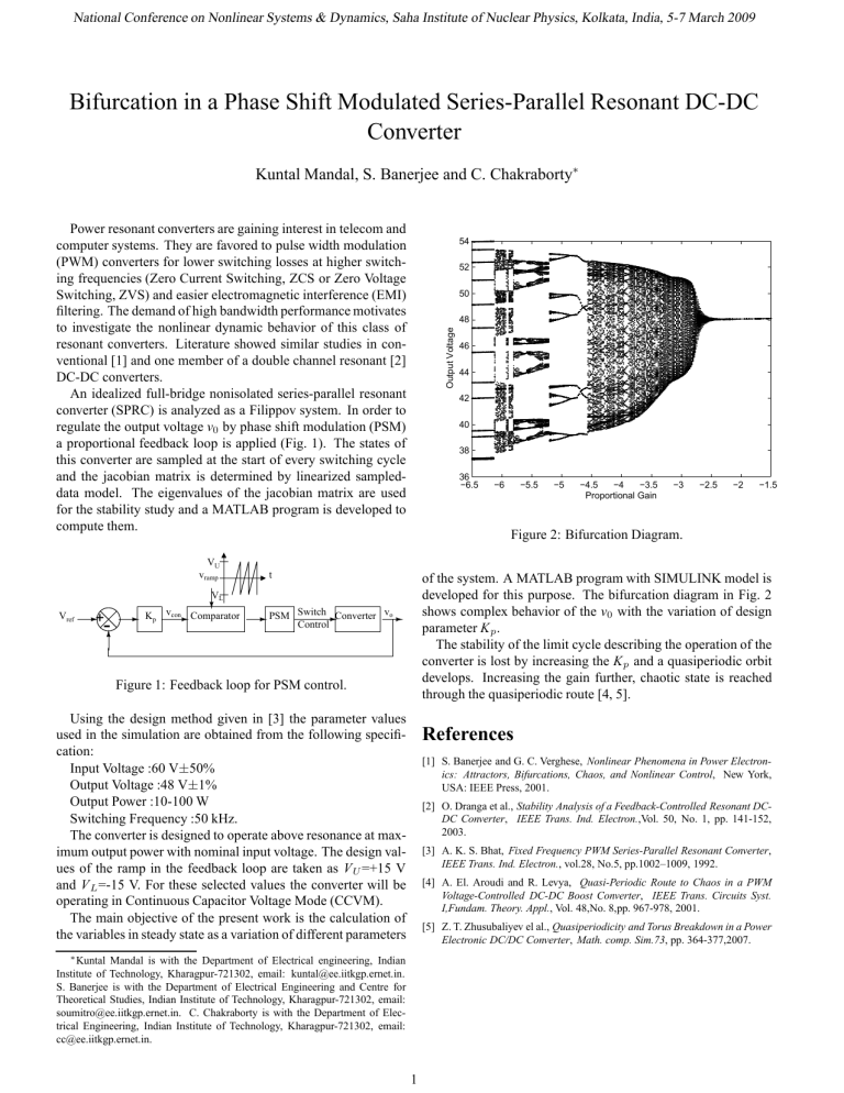
Figure 2: Bifurcation Diagram.
V ref
+
-
K p
V
U v ramp
V
L v con Comparator t
PSM Switch
Control
Converter v o
Figure 1: Feedback loop for PSM control.
of the system. A MATLAB program with SIMULINK model is developed for this purpose. The bifurcation diagram in Fig. 2 shows complex behavior of the v
0 with the variation of design parameter K p
.
The stability of the limit cycle describing the operation of the converter is lost by increasing the K p and a quasiperiodic orbit develops. Increasing the gain further, chaotic state is reached through the quasiperiodic route [4, 5].
Using the design method given in [3] the parameter values used in the simulation are obtained from the following specification:
Input Voltage :60 V ± 50%
Output Voltage :48 V ± 1%
Output Power :10-100 W
Switching Frequency :50 kHz.
The converter is designed to operate above resonance at maximum output power with nominal input voltage. The design values of the ramp in the feedback loop are taken as V
U
=+15 V and V
L
=-15 V. For these selected values the converter will be operating in Continuous Capacitor Voltage Mode (CCVM).
The main objective of the present work is the calculation of the variables in steady state as a variation of different parameters
∗ Kuntal Mandal is with the Department of Electrical engineering, Indian
Institute of Technology, Kharagpur-721302, email: kuntal@ee.iitkgp.ernet.in.
S. Banerjee is with the Department of Electrical Engineering and Centre for
Theoretical Studies, Indian Institute of Technology, Kharagpur-721302, email: soumitro@ee.iitkgp.ernet.in. C. Chakraborty is with the Department of Electrical Engineering, Indian Institute of Technology, Kharagpur-721302, email: cc@ee.iitkgp.ernet.in.
References
[1] S. Banerjee and G. C. Verghese, Nonlinear Phenomena in Power Electron-
ics: Attractors, Bifurcations, Chaos, and Nonlinear Control, New York,
USA: IEEE Press, 2001.
[2] O. Dranga et al., Stability Analysis of a Feedback-Controlled Resonant DC-
DC Converter, IEEE Trans. Ind. Electron.,Vol. 50, No. 1, pp. 141-152,
2003.
[3] A. K. S. Bhat, Fixed Frequency PWM Series-Parallel Resonant Converter,
IEEE Trans. Ind. Electron., vol.28, No.5, pp.1002–1009, 1992.
[4] A. El. Aroudi and R. Levya, Quasi-Periodic Route to Chaos in a PWM
Voltage-Controlled DC-DC Boost Converter, IEEE Trans. Circuits Syst.
I,Fundam. Theory. Appl., Vol. 48,No. 8,pp. 967-978, 2001.
[5] Z. T. Zhusubaliyev el al., Quasiperiodicity and Torus Breakdown in a Power
Electronic DC/DC Converter, Math. comp. Sim.73, pp. 364-377,2007.
1


