Product Specification
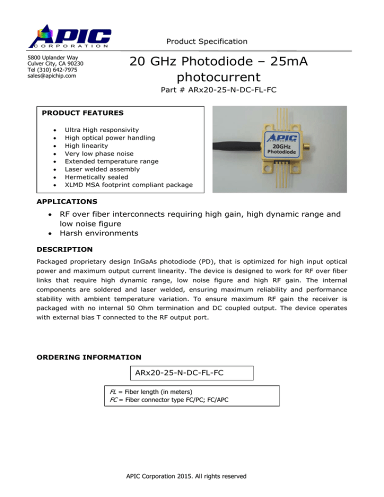
20 GHz Photodiode – 25mA
photocurrent
5800 Uplander Way
Culver City, CA 90230
Tel (310) 642-7975
sales@apichip.com
Part # ARx20-25-N-DC-FL-FC
PRODUCT FEATURES
•
•
•
•
•
•
•
•
Ultra High responsivity
High optical power handling
High linearity
Very low phase noise
Extended temperature range
Laser welded assembly
Hermetically sealed
XLMD MSA footprint compliant package
APPLICATIONS
•
•
RF over fiber interconnects requiring high gain, high dynamic range and
low noise figure
Harsh environments
DESCRIPTION
Packaged proprietary design InGaAs photodiode (PD), that is optimized for high input optical
power and maximum output current linearity. The device is designed to work for RF over fiber
links that require high dynamic range, low noise figure and high RF gain. The internal
components are soldered and laser welded, ensuring maximum reliability and performance
stability with ambient temperature variation. To ensure maximum RF gain the receiver is
packaged with no internal 50 Ohm termination and DC coupled output. The device operates
with external bias T connected to the RF output port.
ORDERING INFORMATION
ARx20-25-N-DC-FL-FC
FL = Fiber length (in meters)
FC = Fiber connector type FC/PC; FC/APC
APIC Corporation 2015. All rights reserved
20 GHz Photodiode – 25mA photocurrent
ABSOLUTE MAXIMUM RATINGS
Parameter
Photodiode
Voltage
Maximum power
ESD output pin
Symbol
V pd
Minimum
Maximum
Units
Condition/Comments
0.5
-6
V
Under 25mW illumination
19
dBm
250
V
P max
V ESD
-250
Fiber bend radius
10
For 25C measurement: Power
= 10*Log(Photo current * Bias
voltage)
mm
ELECTRO-OPTICAL SPECIFICATIONS
Parameter
Symbol
Min.
Wavelength range
λ
1500
Responsivity
R
0.9
Polarization
Dependent
Sensitivity (PDS)
PDL
RF bandwidth
F 3dB
Dark current
I dark
PD reverse bias
V PD
-2
Optical saturation
power
P sat
14
Optical Return
Loss
ORL
-27
Output Reflection
Coefficient
RF Output
Termination
Typ.
Units
1580
nm
0.95
0.1
0
Max.
Condition/Comments
A/W
0.2
22
dB
GHz
50
100
nA
-3
-5
V
dBm
Variation in detected signal
over all polarization states
3 dB point measured
At 25 degrees C ambient
1 dB compression point
when biased at 5V
-30
dB
S 22
NA
dB
Depends on external bias T
R term
NA
Ω
The device is not internally
terminated. The external
bias T sets the RF
termination impedance.
2
APIC Corporation 2015. All rights reserved
20 GHz Photodiode – 25mA photocurrent
MECHANICAL SPECIFICATIONS
Parameter
Symbol
Minimum
Maximum
Units
Height
H
8.6
mm
Area
A
12 x 15
mm2
Condition/Comments
Mounting ears excluded
High Speed
Electrical
Connector
GPPO (Compatible with mini
SMP)
Packaging
Hermetically sealed
Package Heat
Flow
Heat sink on bottom surface
Fiber Pigtail
Length
0.5
2
m
Pigtail
Termination
Custom lengths available
FC/PC;FC/APC SMF28
ENVIRONMENTAL SPECIFICATIONS (preliminary, qualification in progress)
Parameter
Operating
Temperature
Storage
Temperature
Operating
Humidity
Shock
Operational
Vibration
Endurance
Vibration
Reliability
Performance
Minimum
Maximum
Units
-40
+85
°C
-55
+95
°C
0
90
% RH
20 g amplitude and 11 ms
duration, three shocks
each axis, each direction
3.56 Grms one hour each
axis
8.25 Grms one hour each
axis
40,000
Condition/Comments
Case temperature
MIL-STD-810 Method 516, Procedure I.
Non-operational.
MIL-STD-810 Method 514, Procedure
IV.
MIL-STD-810 Method 514, Procedure
IV.
hours
3
APIC Corporation 2015. All rights reserved
20 GHz Photodiode – 25mA photocurrent
RECOMMENDED ELECTRICAL CONNECTION
MECHANICAL DRAWING
4
APIC Corporation 2015. All rights reserved
20 GHz Photodiode – 25mA photocurrent
PIN DESCRIPTION
Pin #
Symbol
1,3,4,5,6,8
2 and 7
RF
Description
Not connected
Gnd
RF
Case Ground
RF signal output
5
APIC Corporation 2015. All rights reserved

