www.em4inc.com
Acousto Optic Modulator
Features
•
•
•
•
•
•
•
Hermetic to MIL-Std 883
Rugged laser welded construction
Fast rise / fall time
High throughput
High contrast ratio
High PER
Wide operating temperature range
Applications
•
•
•
•
Fast optical shutter
Optical switch
Pulse picker
Frequency shifter
Ordering Information
General Description
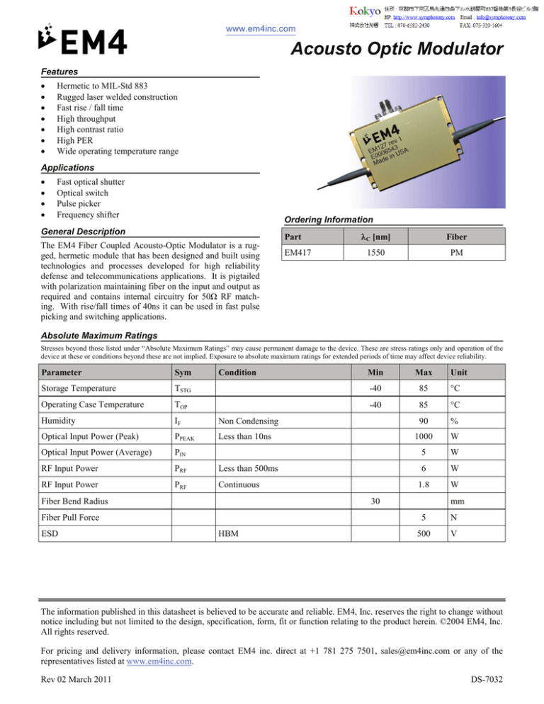
The EM4 Fiber Coupled Acousto-Optic Modulator is a rugged, hermetic module that has been designed and built using
technologies and processes developed for high reliability
defense and telecommunications applications. It is pigtailed
with polarization maintaining fiber on the input and output as
required and contains internal circuitry for 50Ω RF matching. With rise/fall times of 40ns it can be used in fast pulse
picking and switching applications.
Part
EM417
λC [nm]
Fiber
1550
PM
Absolute Maximum Ratings
Stresses beyond those listed under “Absolute Maximum Ratings” may cause permanent damage to the device. These are stress ratings only and operation of the
device at these or conditions beyond these are not implied. Exposure to absolute maximum ratings for extended periods of time may affect device reliability.
Parameter
Sym
Storage Temperature
Condition
Min
Max
TSTG
-40
85
°C
Operating Case Temperature
TOP
-40
85
°C
Humidity
IF
Non Condensing
90
%
Optical Input Power (Peak)
PPEAK
Less than 10ns
1000
W
Optical Input Power (Average)
PIN
5
W
RF Input Power
PRF
Less than 500ms
6
W
RF Input Power
PRF
Continuous
1.8
W
Fiber Bend Radius
30
Fiber Pull Force
ESD
HBM
Unit
mm
5
N
500
V
The information published in this datasheet is believed to be accurate and reliable. EM4, Inc. reserves the right to change without
notice including but not limited to the design, specification, form, fit or function relating to the product herein. ©2004 EM4, Inc.
All rights reserved.
For pricing and delivery information, please contact EM4 inc. direct at +1 781 275 7501, sales@em4inc.com or any of the
representatives listed at www.em4inc.com.
Rev 02 March 2011
DS-7032
Acousto Optic Modulator
Optical, Electrical & Environmental Characteristics
TOP=25°C, beginning of life unless otherwise specified.
Parameter
Sym.
Condition
Min
Typ.
Max
Unit
Operating Wavelength
λC
1530
1550
1570
nm
Input Optical Power (Average)
PIN
1
W
Input Optical Power (Peak)
PPEAK
500
W
On State Transmission
TTRANS
Throughput change over
temperature
ΔT
Temp. range from 10 C to 60C, %
change relative to 25C Transmission
-10
Optical Return Loss
RLOPT
Both input and output signals
40
Polarization Extinction Ratio
PER
PM input and output fiber
17
Rise Time
tr
Fall Time
tf
Contrast Ratio
Cr
RF Matching
ZIN
Electrical Return Loss
RLRF
RF Peak Power
PRF PK
RF Average Power
RF Center Frequency
45
50
%
+10
%
dB
20
dB
10% to 90% signal @1550nm
40
ns
90% to 10% signal @1550nm
40
ns
50
dB
50
Ω
45
-10
dB
4.0
4.5
W
PRF AVG
1.0
1.6
W
RFCF
165
To achieve Contrast Ratio
3.5
MHz
Operating Temperature
10
60
°C
Storage Temperature
-40
85
°C
90
%
Humidity
Non condensing
Air Pressure
Hermeticity
700
MIL-Std 883
1060
kPa
1E-6
ATM cc/s
He
The information published in this datasheet is believed to be accurate and reliable. EM4, Inc. reserves the right to change without
notice including but not limited to the design, specification, form, fit or function relating to the product herein. ©2004 EM4, Inc.
All rights reserved.
For pricing and delivery information, please contact EM4 inc. direct at +1 781 275 7501, sales@em4inc.com or any of the
representatives listed at www.em4inc.com.
Acousto Optic Modulator
Mechanical
Reliability
Parameter
Description
Description
Requirement
Package Body Material
Gold plated kovar or equivalent
Mechanical Shock
MIL-Std 883, Method 2002
RF Connector
SMA, female
Vibration
MIL-Std 883, Method 2007
Fiber Pull
GR-468, 0.5kg minimum strength
All units in mm
Temperature Cycling GR-468, section 5:20
Fiber Characteristics
Description
Specification
Min
Typ
Max
Unit
PM 1550 PANDA or SMF28
Fiber bend radius
30
Fiber length (input & output)
Connectors
None
Fiber Jacket
Acrylate
Stress Rod Alignment
mm
1
m
245
µm
Light aligned to slow axis of both input and output fibers
The information published in this datasheet is believed to be accurate and reliable. EM4, Inc. reserves the right to change without
notice including but not limited to the design, specification, form, fit or function relating to the product herein. ©2004 EM4, Inc.
All rights reserved.
For pricing and delivery information, please contact EM4 inc. direct at +1 781 275 7501, sales@em4inc.com or any of the
representatives listed at www.em4inc.com.


