Electronic regulator for SATK40 series heat interface units
advertisement
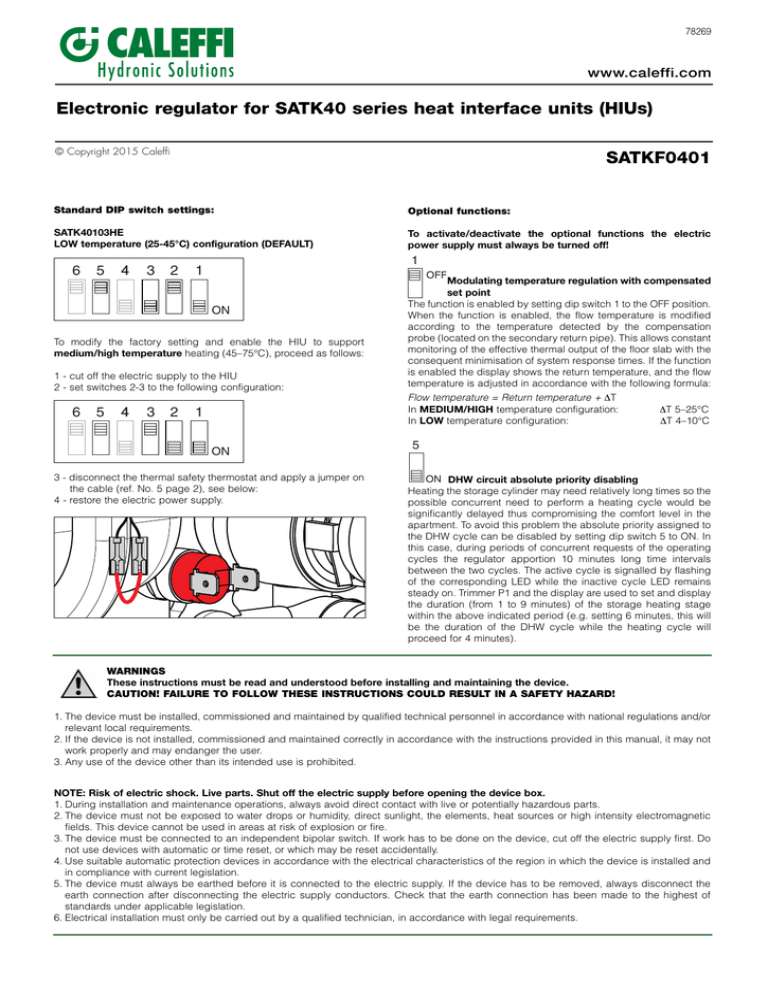
78269 www.caleffi.com Electronic regulator for SATK40 series heat interface units (HIUs) © Copyright 2015 Caleffi SATKF0401 Standard DIP switch settings: Optional functions: SATK40103HE LOW temperature (25-45°C) configuration (DEFAULT) To activate/deactivate the optional functions the electric power supply must always be turned off! 6 5 4 3 2 1 1 ON To modify the factory setting and enable the HIU to support medium/high temperature heating (45–75°C), proceed as follows: 1 - cut off the electric supply to the HIU 2 - set switches 2-3 to the following configuration: 6 5 4 3 2 1 ON 3 - disconnect the thermal safety thermostat and apply a jumper on the cable (ref. No. 5 page 2), see below: 4 - restore the electric power supply. OFF Modulating temperature regulation with compensated set point The function is enabled by setting dip switch 1 to the OFF position. When the function is enabled, the flow temperature is modified according to the temperature detected by the compensation probe (located on the secondary return pipe). This allows constant monitoring of the effective thermal output of the floor slab with the consequent minimisation of system response times. If the function is enabled the display shows the return temperature, and the flow temperature is adjusted in accordance with the following formula: Flow temperature = Return temperature + DT In MEDIUM/HIGH temperature configuration: In LOW temperature configuration: DT 5–25°C DT 4–10°C 5 ON DHW circuit absolute priority disabling Heating the storage cylinder may need relatively long times so the possible concurrent need to perform a heating cycle would be significantly delayed thus compromising the comfort level in the apartment. To avoid this problem the absolute priority assigned to the DHW cycle can be disabled by setting dip switch 5 to ON. In this case, during periods of concurrent requests of the operating cycles the regulator apportion 10 minutes long time intervals between the two cycles. The active cycle is signalled by flashing of the corresponding LED while the inactive cycle LED remains steady on. Trimmer P1 and the display are used to set and display the duration (from 1 to 9 minutes) of the storage heating stage within the above indicated period (e.g. setting 6 minutes, this will be the duration of the DHW cycle while the heating cycle will proceed for 4 minutes). WARNINGS These instructions must be read and understood before installing and maintaining the device. CAUTION! FAILURE TO FOLLOW THESE INSTRUCTIONS COULD RESULT IN A SAFETY HAZARD! 1. The device must be installed, commissioned and maintained by qualified technical personnel in accordance with national regulations and/or relevant local requirements. 2. If the device is not installed, commissioned and maintained correctly in accordance with the instructions provided in this manual, it may not work properly and may endanger the user. 3. Any use of the device other than its intended use is prohibited. NOTE: Risk of electric shock. Live parts. Shut off the electric supply before opening the device box. 1. During installation and maintenance operations, always avoid direct contact with live or potentially hazardous parts. 2. The device must not be exposed to water drops or humidity, direct sunlight, the elements, heat sources or high intensity electromagnetic fields. This device cannot be used in areas at risk of explosion or fire. 3. The device must be connected to an independent bipolar switch. If work has to be done on the device, cut off the electric supply first. Do not use devices with automatic or time reset, or which may be reset accidentally. 4. Use suitable automatic protection devices in accordance with the electrical characteristics of the region in which the device is installed and in compliance with current legislation. 5. The device must always be earthed before it is connected to the electric supply. If the device has to be removed, always disconnect the earth connection after disconnecting the electric supply conductors. Check that the earth connection has been made to the highest of standards under applicable legislation. 6. Electrical installation must only be carried out by a qualified technician, in accordance with legal requirements. Electrical wiring 1 2 3 4 5 6 7 8 6 5 4 3 2 1 1 DHW temperature probe 2 DHW flow meter 3 Flow temperature compensation probe 4 DHW modulating valve actuator 5 Thermal safety thermostat 6 Pressure switch 7 Heating flow temperature probe 8 Heating modulating valve actuator 9 Hearth Pump 10 Power supply 230 V (ac)** 11 13 FUSE 5x20 12 Room thermostat** 13 Fuse 14 Storage cylinder thermostat** 15 Electrical connection box 16 Prepayment connection/HIU enabling ** To be wired during installation (room and cylinder thermostats not supplied) 12 WARNING! DO NOT CONNECT EXTERNAL VOLTAGE SUPPLY TO THESE TERMINALS ATTENZIONE! NON ALIMENTARE IN TENSIONE 16 • • • • Usare solo per collegamento a cod. 789835 Use this wire for connection to code 789835 only À n'utiliser que pour la liaison avec code 789835 Verwenden Sie dieses Gerät nur zum Anschluss an die Art.Nr. 789835 • Gebruik deze enkel voor aansluiting op code 789835 • Utilice solamente para la conexión con cod. 789835 9 15 FUSE 5x20 13 10 NOTA BENE: The pump cable connector is polarised. Insert the connector correcly and do not attempt to force it in the wrong position. 14 11
