Inclined Planes and Pulleys - Liberty Hill Intermediate School
advertisement
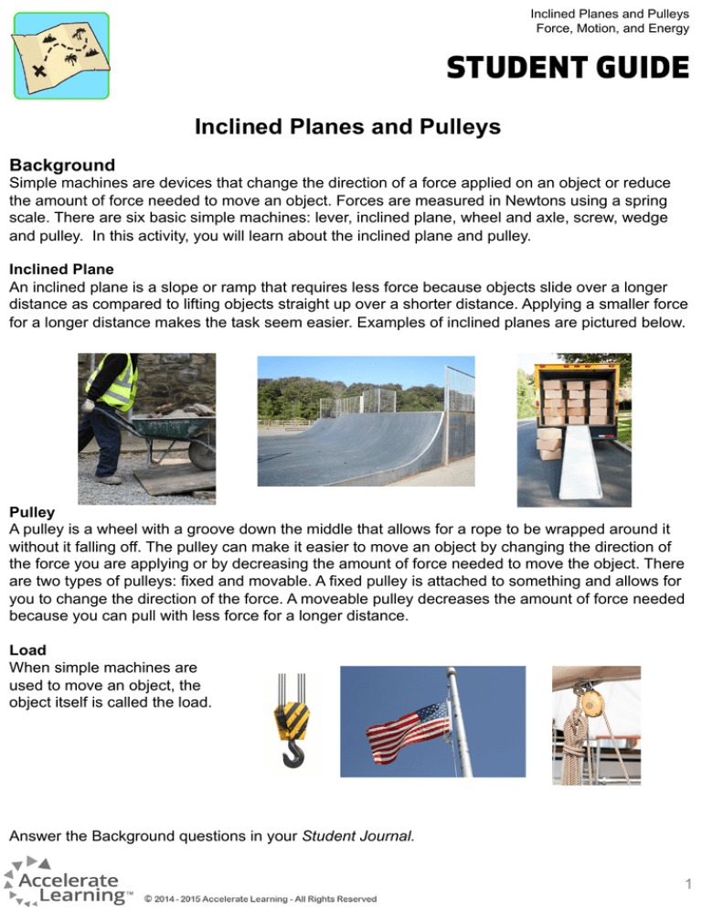
Inclined Planes and Pulleys Force, Motion, and Energy Inclined Planes and Pulleys Background Simple machines are devices that change the direction of a force applied on an object or reduce the amount of force needed to move an object. Forces are measured in Newtons using a spring scale. There are six basic simple machines: lever, inclined plane, wheel and axle, screw, wedge and pulley. In this activity, you will learn about the inclined plane and pulley. Inclined Plane An inclined plane is a slope or ramp that requires less force because objects slide over a longer distance as compared to lifting objects straight up over a shorter distance. Applying a smaller force for a longer distance makes the task seem easier. Examples of inclined planes are pictured below. Pulley A pulley is a wheel with a groove down the middle that allows for a rope to be wrapped around it without it falling off. The pulley can make it easier to move an object by changing the direction of the force you are applying or by decreasing the amount of force needed to move the object. There are two types of pulleys: fixed and movable. A fixed pulley is attached to something and allows for you to change the direction of the force. A moveable pulley decreases the amount of force needed because you can pull with less force for a longer distance. Load When simple machines are used to move an object, the object itself is called the load. Answer the Background questions in your Student Journal. 1 Inclined Planes and Pulleys Force, Motion, and Energy Part I: Using an Inclined Plane In this activity, you will accomplish the task of raising a mass to a distance of 10 cm above the table top with and without the use of a simple machine, the inclined plane. 1. Put 300 g of sand in a plastic bag and seal it. Put the binder clip on the bag so you can hang the bag from the spring scale during the investigation. 2. Mark the one meter board at 0 cm, 20 cm, 40 cm, 60 cm and 100 cm using a meter stick. 3. Stack the textbooks so that they are 10 cm high. 4. Hook the bag of sand to the spring scale and lift the mass straight up to the 10 cm level of the pile of books to get a force reading without the use of a simple machine. 5. Lean the board against the 10 cm high pile of books such that the 20 cm mark rests against the top of the book pile and the 0 cm line is at the bottom of the ramp. One group member will have to hold the board in place. The distance the load travels is now 20 cm in order to raise the load 10 cm above the table height. 6. Measure the angle using a protractor at the base of the inclined plane. Note: it should be less than 90°. 7. Pull the mass up the ramp at a constant speed. It is important to keep the spring scale parallel to the ramp. Stop at the 20 cm mark on the board that corresponds to a distance of 10 cm above the tabletop. 8. Measure and record the force on the spring scale on the Inclined Plane Data Table in your Student Journal. 9. Repeat steps 1 through 7 for the 40 cm (or 0.40m) and 60 cm (or 0.60 m) ramp. Answer the Part I questions in your Student Journal. 2 Inclined Planes and Pulleys Force, Motion, and Energy Part II: Using a Pulley In this activity, you will accomplish the task of raising a mass to a distance of 10 cm above the floor with and without the use of a simple machine, the pulley. A 1. Construct the load bucket of the pulley using the cup, a hole punch, and 20 cm of the twine. Punch a hole about 2 cm from the rim on opposite sides of the cup. Use 5 cm of each end of the 20 cm length of twine to assemble a handle on the cup. Insert each end through the holes in the cup and tie a knot to secure the handle in place. Hook a paperclip on the handle. B 2. Place the bag with 200 g of sand in the cup. Use the spring scale to lift the load bucket a distance of 10 cm above the floor and record your measurement in the data table on the Pulley Data Table in your Student Journal. 3. Place the 30 cm 2 x 2 board on a flat table surface. Be sure that the end with the eyehook attached to the board is at least 8 cm off the end of the table. Secure the board onto the table with duct tape. See diagram A. 4. Assemble a single, fixed pulley system. Be sure to make a loop on each end of the rope and secure it with duct tape. Attach one end of the rope to the paperclip on the bucket and the other end of the rope to the spring scale. C 5. Lift the bucket using the single, fixed pulley. Make sure to pull on the scale until the bucket has been lifted off the ground a distance of 10 cm. See diagram B. Record the force required to lift the bucket with the pulley in the data table of your Student Journal. D 6. Assemble a single, moveable pulley system and lift the load. See diagram C. Record the force required to lift the load using the single, moveable pulley in the data table of your Student Journal. 7. Assemble a system that contains both a single, fixed pulley and a single, moveable pulley and lift the load. See diagram D. Again, record your observations in the data table of your Student Journal. Answer Part II and Reflections and Conclusions questions in your Student Journal. 3
