Datasheet
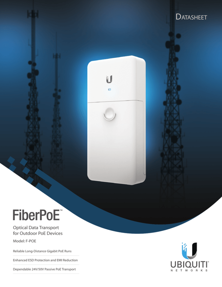
Optical Data Transport
for Outdoor PoE Devices
Model: F-POE
Reliable Long-Distance Gigabit PoE Runs
Enhanced ESD Protection and EMI Reduction
Dependable 24V/50V Passive PoE Transport
Datasheet
Fiber + Power Solution
for Outdoor PoE Devices
Overcome PoE limitations with the FiberPoE™. The
FiberPoE is a low-cost solution for outdoor deployments
that require long-distance runs to reach the PoE device.
Deployments with the FiberPoE also provide significant
EMI and ESD protection over typical PoE installations.
Separate Data and Power Transport
To PoE
Device
PoE is ideal for indoor or short-run installations. However,
for outdoor, long-distance installations, PoE becomes
vulnerable to EMI and is limited to 100 meters with
correlated power loss. With the FiberPoE, data and power
are transported on separate cables to greatly improve
data integrity and enable much longer cable runs.
The FiberPoE provides Gigabit bi‑directional data
transport between twisted-pair Ethernet cable and
fiber optic cable, and injects DC power to the Ethernet
cable for passive PoE. Use one FiberPoE device as an
Fiber‑to‑Ethernet Converter, or a pair of FiberPoE devices to
create a Fiber Bridge.
Fiber Optic Data Transport
Using fiber optic cable for data transport significantly
reduces electrostatic discharge (ESD) failures and
electromagnetic interference (EMI). Data integrity is also
sustained in runs beyond 100 meters, the limit of Ethernet
over twisted‑pair cable.
The FiberPoE supports a 1G SFP module and 24V or 50V
power from a DC power cable or PoE cable.
2
DC
Injection
Fiber
Optic
Integrated Fiber Cable Strain Relief
Datasheet
An integrated strain relief system was thoughtfully designed
to fit inside the FiberPoE cover for added protection and a
cleaner installation.
Fiber Cable
Strain Relief Reel
Cable Strain
Relief Tabs
Application Examples
The following are typical use cases for the FiberPoE.
Data Options
1. Fiber-to-Ethernet Converter One FiberPoE at the top
of the tower is used to convert fiber to Ethernet at the
radio. At the base of the tower, the fiber optic cable
connects directly to a fiber switch or router.
2. Fiber Bridge Two FiberPoE devices, one at the base
and one at the top of the tower, are used to provide a
fiber optic data link for protection from EMI events that
can cause equipment damage or signal integrity issues.
PoE Device
PoE Device
Ethernet Cable
Ethernet Cable
FiberPoE
FiberPoE
Fiber
Optic Cable
Fiber
Optic Cable
FiberPoE
Ethernet Cable
Fiber
Switch/Router
Ethernet
Switch/Router
3
Datasheet
Power Options
The FiberPoE provides passive PoE power to the PoE device. Options for providing power to the FiberPoE include:
DC Power Connect a 24VDC or 50VDC power cable to the Terminal Block.
PoE (Power Only) Connect an Ethernet cable with 24V or 50V (4-pair) PoE to the DC In RJ45 port.
PoE (Power and Data) Connect an Ethernet cable with 24V or 50V (4-pair) PoE to the PoE RJ45 port.
Terminal DC In
Block
(RJ45)
Power Input Port
Terminal Block
(DC Power)
DC In
(Power Only)
PoE
(Power and Data)
4
Input Power
PoE
(RJ45)
Output Power
2-wire DC, 24V
PoE port, 2-pair (4, 5+; 7, 8-), 24V
2-wire DC, 50V
PoE port, 4-pair, 50V
2-pair (4, 5+; 7, 8-), 24V
Terminal Block, 24V
PoE port, 24V, 2-pair (4, 5+; 7, 8-)
4-pair, 24V
Terminal Block, 24V
PoE port, 24V, 4-pair
4-pair, 50
Terminal Block, 50V
PoE port, 50V, 4-pair
2-pair (4, 5+; 7, 8-), 24V
Terminal Block, 24V
4-pair, 24V
Terminal Block, 24V
4-pair, 50V
Terminal Block, 50V
Datasheet
Power Input/Output Examples
Terminal Block Input
Top of Tower
Near the PoE Device
24VDC Input
24V (2-Pair)
Power and Data
to PoE Device
50VDC Input
50V (4-Pair)
Power and Data
to PoE Device
DC In (RJ45) Input
Top of Tower
Near the PoE Device
24V (2-Pair)
24V (2-Pair)
DC Input Power and Data
to PoE Device
50V (4-Pair)
50V (4-Pair)
DC Input Power and Data
to PoE Device
24V (4-Pair)
24V (4-Pair)
DC Input Power and Data
to PoE Device
24/50V
DC Output
24/50V
DC Input
24/50V
Power and Data
to PoE Device
PoE (RJ45) Input
Bottom of Tower
24/50V
DC Output
24/50V Power and Data
from PoE Adapter or PoE Switch
5
Datasheet
Specifications
FiberPoE
Dimensions
196.4 x 93.5 x 32.4 mm
( 7.73 x 3.68 x 1.28")
Weight
288 g
(10.2 oz)
Enclosure
White Polycarbonate
Interface Connections
(1) 1 Gbps SFP Port
(1) DC Terminal Block
(1) DC RJ45 Port DC Injection
(1) 1000 Mbps Ethernet PoE Port
Typical Power Consumption
Power Method
1.5W
DC Terminal Block, 2-Wire, 24VDC or 50VDC
DC In RJ45 Port, 2-Pair (4, 5+; 7, 8-) (24VDC Input), or
4-Pair (24VDC or 50VDC Input) Passthrough
PoE RJ45 Port, 2-Pair (4, 5+; 7, 8-) (24VDC Input), or
4-Pair (24VDC or 50VDC Input) PoE Passthrough
PoE Output
PoE RJ45 Port, 2-Pair (4, 5+; 7, 8-) (24VDC), or
4-Pair (24VDC or 50VDC) PoE
DC Output
Terminal Block, 2-Wire (24VDC or 50VDC)
16 to 57V
Input DC Voltage
LED
White: Power On
Blue: Connected
Blue (Flashing): Activity
Operating Temperature
-30 to 60° C
(-22 to 140° F)
Operating Humidity
10 to 95% Noncondensing
ESD/EMP Protection
± 24KV Contact / Air for Ethernet
PH030916
Certifications
6
Specifications are subject to change. Ubiquiti products are sold with a limited warranty described at: www.ubnt.com/support/warranty
©2015-2016 Ubiquiti Networks, Inc. All rights reserved. Ubiquiti, Ubiquiti Networks, the Ubiquiti U logo, the Ubiquiti beam logo, and FiberPoE are
trademarks or registered trademarks of Ubiquiti Networks, Inc. in the United States and in other countries.
All other trademarks are the property of their respective owners.
CE, FCC, IC
www.ubnt.com


