Paragon Defrost Timers 9145/9045: Universal Control Solutions
advertisement
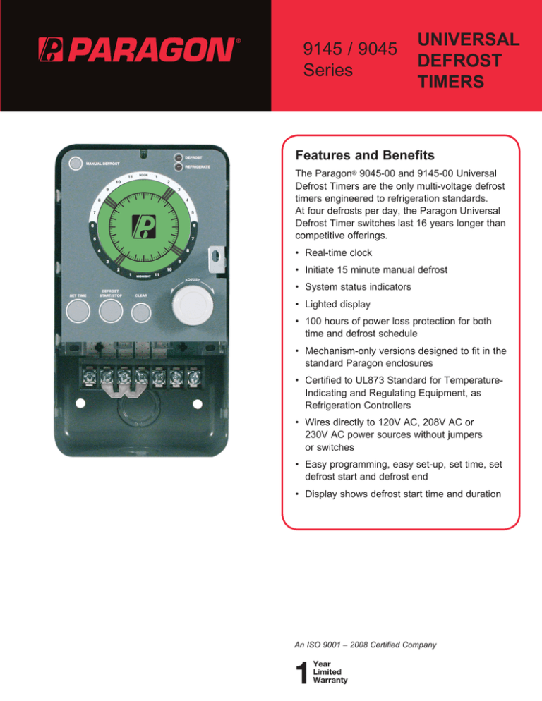
9145 / 9045 Series UNIVERSAL DEFROST TIMERS Features and Benefits The Paragon® 9045-00 and 9145-00 Universal Defrost Timers are the only multi-voltage defrost timers engineered to refrigeration standards. At four defrosts per day, the Paragon Universal Defrost Timer switches last 16 years longer than competitive offerings. • Real-time clock • Initiate 15 minute manual defrost • System status indicators • Lighted display • 100 hours of power loss protection for both time and defrost schedule • Mechanism-only versions designed to fit in the standard Paragon enclosures • Certified to UL873 Standard for TemperatureIndicating and Regulating Equipment, as Refrigeration Controllers • Wires directly to 120V AC, 208V AC or 230V AC power sources without jumpers or switches • Easy programming, easy set-up, set time, set defrost start and defrost end • Display shows defrost start time and duration An ISO 9001 – 2008 Certified Company 1 Year Limited Warranty UNIVERSAL DEFROST TIMERS 9145 / 9045 Series Ordering Information 9145-00 9145-00M 9045-00 9045-00M Time Time Time Time Initiate/Temperature, Pressure Terminate Defrost Timer with Metal Enclosure Initiate/Temperature, Pressure Terminate Defrost Timer – Mechanism Only Initiate/Time Terminate Defrost Timer with Metal Enclosure Initiate/Time Terminate Defrost Timer – Mechanism Only 9145 Terminal Data* Terminal Relay Contact Relay Rating A B SPDT SPDT NC NO Contact Contact 15A resistive @ 30A resistive @ 120 VAC to 240 VAC 120 VAC to 240 VAC 1/4HP @ 120 VAC, 1HP @ 120 VAC, 1/2HP @ 208 VAC 2HP @ 208 VAC to 240 VAC to 240 VAC Device Connections Fan (Typical) Compressor (Optional) Defrost Device (Typical) C SPDT COMM Contact D SPST NO Contact L1 Power to timer and to Defrost Termination Device E SPST COMM Contact 30A resistive @ 120 VAC to 240 VAC 1HP @ 120 VAC, 2HP @ 208 VAC to 240 VAC F L2/N Power in to timer G Defrost Termination Device Input L2/N side Compressor (Typical) Fan (Optional) Defrost Termination Switch * 9145 is a general purpose defrost timer and can be used for both Time Initiate/Time Terminate and Time Initiate/Temperature, Pressure Terminate 9045 Terminal Data* Terminal Relay Contact Relay Rating A SPST #1 NC Contact 30A resistive @ 120 VAC to 240 VAC 1HP @ 120 VAC, 2HP @ 208 VAC to 240 VAC Device Connections B SPST #1 COMM Contact C LI Power in to timer D SPST #2 NO Contact Compressor (Typical) E SPST #2 COMM Contact 30A resistive @ 120 VAC to 240 VAC 1HP @ 120 VAC, 2HP @ 208 VAC to 240 VAC F L2/N Power in to timer G No Connection Defrost Drive (Typical) Specifications Input Power Storage Temperature 120/208–240 VAC 60 Hz (+10, -15%) -40°F to 140°F (-40°C to 60°C) Power Consumption Outside Dimensions 6VA max, Defrost termination switch (terminal “G”) input impedance to terminal C: 85kΩ +/- 5% Individual unit 4.40”W x 7.82”H x 3.80”D Operating Voltage 102 VAC min to 132 VAC max @ 60 Hz 176.8 VAC min to 264 VAC max @ 60Hz NOTE: No user-required adjustments to switch between the high and low voltage. Ambient Operating Conditions -40°F to 131°F (-40°C to 55°C); 0 to 95% RH (non-condensing) Individual unit (in shipping box) 4.75”W x 8.875”H x 4.75”D Individual Case Shipping Weight 3.2 lbs Agency Approvals c-UR-us Recognized Component – Models 9045-00M & 9145-00M c-UR-us Listed Product – Models 9045-00 & 9145-00 UNIVERSAL DEFROST TIMERS 9145 / 9045 Series Conversion Diagrams for Paragon Mechanical Controls Convert 8045 to 9045 Convert 8041 to 9145 8041 N 1 3 9145 A B 2 C 8045 2 4 D 4 X E F G 9045 A Convert 8141 to 9145 8141 N 1 3 9145 A B C D 8143 1 X E B F 1 3 C D X E F Convert 8143 to 9145 4 2 N N 3 G 9145 A B 2 4 C D X E F G Convert 8145 to 9145 8145 3 1 9145 A 191 E. North Avenue Carol Stream Illinois 60188 USA Customer Service Telephone 1.800.304.6563 Customer Service Facsimile 1.800.426.0804 HVACCustomerService@InvensysControls.com B 4 2 C D X N E F For Technical Service Telephone 1.800.445.8299 Facsimile 1.630.260.7294 TechnicalService@InvensysControls.com G InvensysTM, Paragon®, and Uni-Line® are trademarks of Invensys plc., its subsidiaries and/or affiliated companies. All other brands mentioned in this document may be the trademarks of their respective owners. www.Uni-Line.com www.InvensysControls.com ©2009 Invensys Controls 11/09 – 150-1893D UNIVERSAL DEFROST TIMERS 9145 / 9045 Series Applications and Wiring Diagrams 9045 AIR DEFROST Time Initiated Time Terminated 9145 ELECTRIC DEFROST Time Initiated Temperature Terminated TIMER A B C D E F TIMER Terminal "G" Defrost Termination Sense Circuitry G A B C D E F G T'STAT T'STAT DEFROST TERMINATION/FAN COMPRESSOR FAN COMPRESSOR HEATER L, L1 L, L1 9045 ELECTRIC DEFROST Time Initiated Time Terminated 9145 AIR DEFROST Time Initiated Time Terminated TIMER A B C N, L2 N, L2 D E F TIMER Terminal "G" Defrost Termination Sense Circuitry G A B C D T'STAT E F G T'STAT COMPRESSOR HEATER COMPRESSOR L, L1 L, L1 N, L2 N, L2 9145 ELECTRIC DEFROST Time Initiated Time Terminated TIMER Terminal "G" Defrost Termination Sense Circuitry A B C D E F T'STAT FAN COMPRESSOR HEATER L, L1 N, L2 G
