Material, Process, and Device Development of GaN
advertisement
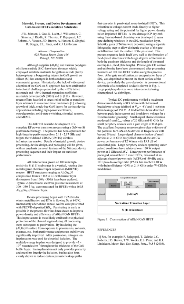
Material, Process, and Device Development of GaN-based HFETs on Silicon Substrates J.W. Johnson, J. Gao, K. Lucht, J. Williamson, C. Strautin, J. Riddle, R. Therrien, P. Rajagopal, J.C. Roberts, A. Vescan, J.D. Brown, A. Hanson, S. Singhal, R. Borges, E.L. Piner, and K.J. Linthicum Nitronex Corporation 628 Hutton Street, Suite 106 Raleigh, NC 27606 Although sapphire (Al2O3) and various polytypes of silicon carbide (SiC) have been the most widely employed substrate materials for gallium nitride (GaN) heteroepitaxy, a burgeoning interest in GaN growth on silicon (Si) has emerged in both academic and commercial groups. Historically, the lack of widespread adoption of the GaN-on-Si approach has been attributable to technical challenges presented by the ~17% lattice mismatch and ~56% thermal expansion coefficient mismatch between GaN (0001) and Si (111). However, recent efforts have led to stress-relief buffer or transition layer schemes to overcome these limitations [1], allowing growth of thick, crack-free GaN layers for various device applications including high-power electronics, optoelectronics, solid-state switching, chemical sensors, and MEMS. This talk will describe development of a complete RF power transistor process using a GaN-on-Si platform technology. The process has been optimized for high-linearity performance from 2.11 - 2.17 GHz and targets the wideband CDMA (UMTS) wireless infrastructure market. Details of material growth, device processing, device design, and packaging will be given, with an emphasis on novel features of the Nitronex device processing sequence and their impact on transistor performance. All material was grown on 100 mm highresistivity Si (111) substrates in a vertical, rotating disc metalorganic chemical vapor deposition (MOCVD) reactor. HFET structures ranging in AlxGa1-xN composition from x = 0.2 to 0.3 with barrier layer thicknesses from 160Å - 300Å have been explored. Typical 2-dimensional electron gas sheet resistances of 300 - 350 Ω/sq. were measured for HFETs with a 160Å Al0.26Ga0.74N barrier layer. that can exist in passivated, mesa-isolated HFETs. This reduction in leakage current leads directly to higher voltage rating and the potential for higher power density in ion implanted HFETs. A low-damage ICP dry etch using fluorine-based chemistry was developed to open gate-defining windows in the SiNx passivation layer. Schottky gates of Ni/Au were deposited using a separate lithography step to allow dielectric overlap of the gate metallization onto the surface of the passivant. This process sequence lends itself very well to the formation of field-plated structures with design degrees of freedom in both the passivant thickness and the length of the metal overlap (i.e., field plate length). Precise gate CD control and uniformity have been demonstrated after processing hundreds of 100 mm HFET wafers using this process flow. After gate metallization, an encapsulation layer of SiNx was deposited to protect the front surface of the device, particularly the gate electrode. A cross-sectional schematic of a completed device is shown in Fig. 1. Large periphery devices were interconnected using electroplated Au airbridges. Typical DC performance yielded a maximum drain current density of 0.9 A/mm with 3-terminal breakdown voltage (defined at Vgs = -8V and 1 mA/mm drain leakage) of 150 V. A tradeoff has been identified between peak drain current and breakdown voltage for a fixed transistor geometry. Small-signal characterization produced fT and fmax values of 20 GHz and 41 GHz for small periphery devices with a gate length of 0.56 m. The excellent frequency response gives clear evidence of the potential for GaN-on-Si devices at frequencies well beyond S-band. Large-signal characterization of small devices at 2.14 GHz has yielded state-of-the-art CW power performance of 12 W/mm with 15.3 dB of associated gain. Large periphery devices operating under pulsed conditions have achieved over 120 W output power at 2 GHz and 28V. Linear power performance of packaged, unmatched 16 mm HFETs, measured at an adjacent channel power ratio (ACPR) of -39 dBc and a 10:1 peak-to-average ratio (PAR), has reached >10 W with drain efficiency >29% at 2.14 GHz under W-CDMA modulation. Encapsulation Layer Interconnect Source SiNx Drain (Al,Ga)N implanted Device processing began with Ti/Al/Ni/Au ohmic metallization and RTA in flowing N2 at 840ºC. Immediately after ohmic anneal, wafers were passivated with PECVD-deposited SiNx. Passivating as early as possible in the process flow has been shown to improve power density and efficiency of AlGaN/GaN HFETs. This improvement is most likely attributable to physical protection of the channel region during all processing steps subsequent to passivation. By insulating the (Al,Ga)N surface from exposure to photoresists, solvents, plasmas, etc., both performance and process stability are significantly improved. After passivation, nitrogen ion implantation was used for electrical isolation. The multiple-energy implant was designed to provide ~5 × 10²⁰ vacancies/cm-3 throughout the thickness of the GaN buffer layer. Ion implantation not only provides planarity and excellent interdevice isolation, but has also been clearly shown to reduce certain parasitic leakage paths Gate implanted Nucleation / Transition Layer Si (111) Substrate Figure 1. Cross section of AlGaN/GaN HFET REFERENCES [1] See, for example: P. Rajagopal, T. Gehrke, J.C. Roberts, J.D. Brown, T.W. Weeks, E.L. Piner, and K.J. Linthicum, Mater. Res. Soc. Symp. Proc., 743 3 (2003).
![Structural and electronic properties of GaN [001] nanowires by using](http://s3.studylib.net/store/data/007592263_2-097e6f635887ae5b303613d8f900ab21-300x300.png)

