Application Specification
114-13158
MULTILOCK* .040/2.8 Hybrid Connectors
NOTE
08 JUL 08
All numerical values are in metric units [with U.S. customary units in brackets]. Dimensions are in millimeters [and
Rev B
_
inches]. Unless otherwise specified, dimensions have a tolerance of +0.13 [+.005] and angles have a tolerance of +2 .
i
Figures and illustrations are for identification only and are not drawn to scale.
1. INTRODUCTION
This specification covers the requirements for application of MULTILOCK .040/2.8 hybrid connectors used in
the automotive industry. The hybrid connectors consist of 38– and 54–way (position) horizontal printed circuit
(pc) board–mount hybrid cap assemblies and 22–way wire–termination hybrid plug assembly. The cap
assembly is pre–loaded with right–angle solder post (signal and power) contacts with signal contact centerline
spacing of 2.5 [.098]. The plug assembly accepts 2.8 series unsealed (power) receptacle contacts in circuit
cavities 1 and 12 and .040 Type II series (signal) receptacle contacts in the remaining circuit cavities.
When corresponding with personnel, use the terminology provided in this specification to facilitate your
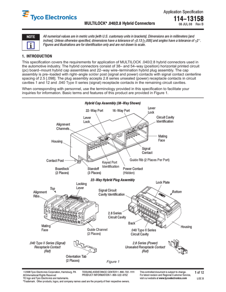
inquiries for information. Basic terms and features of this product are provided in Figure 1.
Hybrid Cap Assembly (38-Way Shown)
22-Way Port
Lever
16-Way Port
Lock
Lever
Circuit Cavity
Lock
Identification
Alignment
Channels
Mating
Face
Housing
Signal
Contact
Contact Post
Guide Rib (2 Places Per Port)
Keyed Port
Boardlock
Standoff
(2 Places)
(3 Places)
Identification
Power Contact
(Hidden)
22-Way Hybrid Plug Assembly
Lock Plate
Locking
Lever
Top
Alignment
Signal Circuit
Bottom
Cavity Identification
Ribs
2.8 Series
Circuit Cavity
Back
Mating
Housing
Face
Guide Channel
.040 Type II Series
(2 Places)
Circuit Cavity
.040 Type II Series (Signal)
2.8 Series (Power)
Receptacle Contact
Unsealed Receptacle Contact
(Ref)
(Ref)
Orientation Tab
(2 Places)
E
2008 Tyco Electronics Corporation, Harrisburg, PA
All International Rights Reserved
Figure 1
TOOLING ASSISTANCE CENTER 1-800-722-1111
This controlled document is subject to change.
PRODUCT INFORMATION 1-800-522-6752
For latest revision and Regional Customer Service,
TE logo and Tyco Electronics are trademarks.
*Trademark. Other products, logos, and company names used are the property of their respective owners.
visit our website at www.tycoelectronics.com
1 of 12
LOC B
MULTILOCK .040/2.8 Hybrid Connectors
114-13158
The hybrid plug assembly consists of a housing and a side–type lock plate. End signal circuit cavities are
marked on the back of the housing for identification. Each contact is held in the circuit cavity when the internal
locking mechanism engages the locking surface of the contact. When engaged (in the “latched” position), the
lock plate ensures that all contacts are seated and provides a secondary lock to secure them in place.
NOTE
Application requirements for the contacts are covered in 114-5159 for the .040 Type II series and 114-13013 for the
unsealed 2.8 series.
i
Each hybrid cap assembly features boardlocks to provide stability for placement on the pc board and standoffs
to facilitate pc board cleaning after soldering. The hybrid cap assemblies can be placed on the pc board
manually or by using an automatic machine.
The 38–way hybrid cap assembly has one 22–way port and one 16–way port. The 54–way hybrid cap
assembly has two 22–way ports and one 10–way port. Each port accepts a plug assembly having the same
number of circuit cavities. Each port features alignment channels that accept the alignment ribs of the plug
assembly for proper mating. The guide ribs and guide channels help to guide the plug assembly into the port of
the hybrid cap assembly. The connectors have locking features for harness retention.
NOTE
Application requirements for the 10-way plug assembly is covered in 411-5763, and application requirements for the
16-way plug assembly is covered in 412-5475.
i
The 38-way and 54-way hybrid cap assemblies and 22-way hybrid plug assembly are covered in this application
specification.
Keying is provided for the 22–way ports of the 54–way hybrid cap assembly. These ports have keyed
alignment channels that accept the keyed alignment ribs of a 22–way hybrid plug assembly for proper port
selection when mating. These ports are embossed with a letter (A or B) for key identification, and the housings
are color–coded corresponding to the key for visual identification.
2. REFERENCE MATERIAL
2.1. Revision Summary
S Updated application specification to corporate requirements
S Changed base part number in Paragraph 2.2
2.2. Customer Assistance
Reference Product Base Part Number 1438789 and Product Code 0417 are representative of MULTILOCK
.040/2.8 hybrid connectors. Use of these numbers will identify the product line and expedite your inquiries
through a service network established to help you obtain product and tooling information. Such information can
be obtained through a local Representative (Field Service Engineer, Field Applications Engineer, etc.) or, after
purchase, by calling PRODUCT INFORMATION at the number at the bottom of page 1.
2.3. Drawings
Customer Drawings for product part numbers are available from the service network. If there is a conflict
between the information contained in the Customer Drawings and this specification or with any other technical
documentation supplied, the information contained in the Customer Drawings takes priority.
2.4. Manuals
Manual 402–40 can be used as a guide to soldering. This manual provides information on various flux types
and characteristics with the commercial designation and flux removal procedures. A checklist is included in the
manual as a guide for information on soldering problems.
2.5. Specifications
Product Specifications (108–series) provides product performance and test information, and Application
Specifications (114– and 412–series) provides product description and application requirements. Documents
available which pertain to this product are:
108–2217
2 of 12
.040 II/2.8 Unsealed Hybrid MULTILOCK Connector System
Tyco Electronics Corporation
Rev B
MULTILOCK .040/2.8 Hybrid Connectors
108–5342
114-13158
.040 II/.070 II Hybrid I/O MK–II Connector for Wire–to–Board Termination
114–5159 Crimping .040 II Series Tab and Receptacle Contact
114–13013 2.8mm Terminal System (Sealed and Unsealed)
2.6. Instructional Material
Instruction Sheets (408– and 411–series) provide product assembly instructions or tooling setup and operation
procedures. Documents available which pertain to this product are:
408–9817 Handling of Reeled Products
408–10027 Disengaging the Lock Plate of 22–Way .040/2.8 Hybrid Plug Assemblies
411–5763
411–5287
411–5288
.040 III High Density Connector
Extraction Tool 755430–2 for Extracting .070 Series Contact
Extraction Tool 755430–1 for Extracting .040 Series Contact
3. REQUIREMENTS
3.1. Safety
Do not stack product shipping containers so high that the containers buckle or deform.
3.2. Storage
A. Reeled Products
Coil wound reels should be stored horizontally and traverse wound reels should be stored vertically.
B. Ultraviolet Light
Prolonged exposure to ultraviolet light may deteriorate the chemical composition used in the connector
material.
C. Shelf Life
The connectors should remain in the shipping containers until ready for use to prevent deformation to the
contacts. The connectors should be used on a first in, first out basis to avoid storage contamination that
could adversely affect performance.
D. Chemical Exposure
Do not store connectors near any chemical listed below as they may cause stress corrosion cracking in
the contacts.
Alkalies
Amines
NOTE
Ammonia
Carbonates
Citrates
Nitrites
Phosphates Citrates
Sulfur Nitrites
Sulfur Compounds
Tartrates
Where the above environmental condition exists, it is recommended using phosphor-bronze contacts.
i
3.3. Contact Loading
A. Disengage Lock Plate
The lock plate of the hybrid plug assembly must be disengaged (in the pre–latch position) before any
contacts can be inserted. The lock plate is disengaged when both ends are raised slightly (approximately
1.3 [.051]) and evenly from the housing. See Figure 2.
NOTE
408-10027 provides instruction for disengaging and engaging the lock plate.
i
B. Insert Contact
The contact must be inserted into the contact cavity at the back of the hybrid plug assembly. The contact
must be oriented so that the orientation tabs face the locking lever as shown in Figure 2, Detail A.
Rev B
Tyco Electronics Corporation
3 of 12
MULTILOCK .040/2.8 Hybrid Connectors
114-13158
Contact Loading
1.3 [.051]
Lock Plate Disengaged
Approx
Lock Plate Engaged
Flush
(Pre-Latch Position)
(Latched Position)
Housing
1.3 [.051]
Approx
Housing
Locking Lever
Locking Lever
Back of
Detail A
Hybrid Plug Assembly
Orientation Tab
(2 Places)
Detail B
Housing Lance
Lock Plate
Figure 2
NOTE
The contact cavities and contacts have polarization features that prevent the contact from being inserted upside-down.
i
When the contact is fully inserted (there should be an audible click), the locking surface of the contact
(located between the orientation tabs) will engage the housing lance of the hybrid plug assembly and
prevent backing out during mating of the connectors. After insertion, it is recommended to pull back lightly
on the wire to ensure that the contact is seated. See Figure 2, Detail B.
CAUTION
Contacts must not be forced to be seated.
!
C. Engage Lock Plate
After all contacts are seated, the lock plate of the hybrid plug assembly must be engaged (in the “latched”
position). The lock plate is engaged when it is flush with the housing. If the lock plate does not engage,
this indicates that all contacts are not seated. See Figure 2.
3.4. Contact Extraction
The lock plate of the hybrid plug assembly must be disengaged (in the pre–latch position) before removing any
contacts. The lock plate is disengaged when both ends are raised slightly (approximately 1.3 [.051]) and evenly
from the housing as shown in Figure 2.
4 of 12
Tyco Electronics Corporation
Rev
B
MULTILOCK .040/2.8 Hybrid Connectors
114-13158
An extraction tool (refer to Section 5) must be used to extract a contact from the housing.
408-10027 provides instruction for disengaging and engaging the lock plate. The instruction sheet packaged with the
tool provides instruction for extracting the contacts.
NOTE
i
3.5. PC Board
A. Material and Thickness
The pc board material shall be glass epoxy (FR–4 or G–10). Recommended pc board thickness is 1.57
[.062]. Board thickness may vary; however, it is recommended that a minimum of 1.02 [.040] of the
contact post protrude from the pc board.
Contact PRODUCT INFORMATION at the number listed at the bottom of page 1 for suitability of other board materials
and thicknesses.
NOTE
i
B. Tolerance
Maximum allowable bow of the pc board shall be 0.03 [.001] over the length of the hybrid cap assembly.
C. Pads
The pc board circuit pads must be solderable in accordance with Test Specification 109–11.
D. Hole Dimensions
The contact holes must be drilled to specific dimensions to prevent stubbing during placement of the
hybrid cap assembly on the pc board and to ensure optimum continuity for circuits. The contact holes can
be used with or without plating. The plating type and thickness and finished hole size must be as stated in
Figure 3.
The boardlock holes must be drilled to the dimensions given in Figure 3.
Contact Hole
ÉÉÉ
É
Ç
ÉÉÉ
É
Ç
ÉÉÉ
É
Ç
ÉÉÉ
É
Ç
ÉÉÉ
É
Ç
1.25 [.049] for .040 Type II Series Contact
1.52 [.060] for 2.8 Series Contact
Finished Hole Diameter (After Plating)
.051+.025 [.002+.001]
Copper Plating (Max Hardness 150 Knoop)
Pad Diameter
Ç
É
ÉÉÉÉ
É
Ç
ÉÉÉÉ
É
Ç
ÉÉ
ÉÉÉÉ
É
Ç
ÉÉ
ÉÉÉÉ
É
Ç
ÉÉ
ÉÉÉÉ
ÉÉ
ÉÉ
0.008 [.0003] (Min)
Tin-Lead Plating
Drilled Hole Diameter
(As Required)
(As Required)
Boardlock Hole
ÉÉÉ
ÉÉÉ
ÉÉÉ
ÉÉÉ
ÉÉÉ
ÉÉÉ
3.1 [.122]
Drilled Hole Diameter
Figure 3
Rev
B
Tyco Electronics Corporation
5 of 12
MULTILOCK .040/2.8 Hybrid Connectors
114-13158
E. Layout
The boardlock holes and contact holes in the pc board must be precisely located to ensure proper
placement and optimum performance of the hybrid cap assembly. The pc board layout must be designed
using the dimensions provided on the customer drawing for the specific hybrid cap assembly. Reference
samples of the recommended pc board layout are shown in Figure 4.
Sample Recommended PC Board Layout
(Connector Side)
Note:
Not to scale. Dimensions are in millimeters.
38-Way Hybrid Cap Assembly
54-Way Hybrid Cap Assembly
Figure 4
3.6. Cap Assembly Placement
CAUTION
Hybrid cap assemblies should be handled only by the housing to avoid deformation, contamination, or damage to the
contact posts or boardlocks.
!
A. Registration
The hybrid cap assembly number one contact position must be aligned with the number one circuit hole on
the pc board. When placing hybrid cap assemblies on the pc board, make sure that the contact posts and
boardlocks are aligned with matching holes before seating the cap assembly onto the pc board. Refer to
Figure 5.
B. Seating
The hybrid cap assembly standoffs must be fully seated on the pc board as shown in Figure 5.
6 of 12
Tyco Electronics Corporation
Rev
B
MULTILOCK .040/2.8 Hybrid Connectors
114-13158
Placement of Hybrid Cap Assembly
Number One Position
PC Board
Boardlocks Through
Holes in PC Board
Contact Posts Through
Holes in PC Board
Standoffs Fully Seated on PC Board
Figure 5
C. Insertion Force
The maximum force required to seat the cap assembly onto the pc board is 41.15 N [9.25 lb–force] per
hybrid cap assembly.
3.7. Soldering
A. Flux Selection
The contact posts and boardlocks must be fluxed prior to soldering with a mildly active, rosin base flux.
Selection of the flux will depend on the type of pc board and other components mounted on the board.
Additionally, the flux must be compatible with the wave solder line, manufacturing, health, and safety
requirements. Call PRODUCT INFORMATION at the number at the bottom of page 1 for consideration of
other types of flux. Flux that is compatible with the hybrid cap assemblies is provided in Figure 6.
COMMERCIAL DESIGNATION
FLUX TYPE
ACTIVITY
RMA
Mild
RESIDUE
Noncorrosive
KESTER
ALPHA
186
611
Figure 6
B. Process
The hybrid cap assemblies can be soldered using wave soldering, vapor phase (VPR), double–sided
non–focused infrared reflow (IR), or equivalent soldering techniques. It is recommended using SN60 or
SN62 solder. The temperatures and exposure time shall be as specified in Figure 7.
SOLDERING PROCESS
TEMPERATURE (Max)
TIME
Wave
260_C [500_F]
5 Seconds
VPR
215_C [419_F]
5 Minutes
IR
260_C [500_F]
40 Seconds
Figure 7
C. Cleaning
After soldering, removal of fluxes, residues, and activators is necessary. Consult with the supplier of the
solder and flux for recommended cleaning solvents. Cleaners must be free of dissolved flux and other
contaminants. Common cleaning solvents with times and temperatures that will not affect these
connectors is specified in Figure 8.
CAUTION
Even when using no clean" solder paste, it is imperative that the contact interface be kept clean of flux and residue,
since it acts as an insulator. Flux may migrate under certain conditions with elevated temperatures and, therefore,
!
Rev B
cleaning is necessary.
Tyco Electronics Corporation
7
of 12
MULTILOCK .040/2.8 Hybrid Connectors
DANGER
114-13158
Consideration must be given to toxicity and other safety requirements recommended by the solvent manufacturer.
Refer to the manufacturer's Material Safety Data Sheet (MSDS) for characteristics and handling of cleaners.
Trichloroethylene and Methylene Chloride is not recommended because of harmful occupational and environmental
effects. Both are carcinogenic (cancer-causing).
CLEANER
NAME
TYPE
TIME
TEMPERATURE
(Minutes)
(Maximum)
ALPHA 2110
Aqueous
1
132_C [270_F]
BIOACT EC-7
Solvent
5
100_C [212_F]
Butyl CARBITOL
Solvent
1
Ambient Room
Isopropyl Alcohol
Solvent
5
100_C [212_F]
KESTER 5778
Aqueous
5
100_C [212_F]
KESTER 5779
Aqueous
5
100_C [212_F]
LONCOTERGE 520
Aqueous
5
100_C [212_F]
LONCOTERGE 530
Aqueous
5
100_C [212_F]
Terpene Solvent
Solvent
5
100_C [212_F]
Figure 8
NOTE
If you have a particular cleaning solvent that is not listed, contact PRODUCT INFORMATION at the number at the
bottom of page 1.
i
D. Drying
When drying cleaned assemblies and pc boards, temperature limitations must not be exceeded: –55_ to
105_C [–68_ to 221_F]. Excessive temperatures may cause housing degradation.
3.8. Connector Spacing
Care must be used to avoid interference between adjacent connectors and other components. The minimum
distance between cap assemblies to ensure proper placement (side–to–side) and ability of mating
(face–to–face) is provided in Figure 9.
Side-to-Side Recommended Distance
1.2 [.047] Min
Face-to-Face Recommended Distance
40 [1.57] Min
Figure 9
8
of 12
Tyco Electronics Corporation
Rev B
MULTILOCK .040/2.8 Hybrid Connectors
NOTE
114-13158
If robotic equipment is used for placement of the cap assemblies, space must be allowed for the grippers.
i
3.9. Checking Installed Hybrid Cap Assembly
All solder joints should conform to those specified in Workmanship Specification 101–21 and all other
requirements specified in this document. The standoffs must be seated on the pc board not exceeding the
dimension shown in Figure 10.
The installed hybrid cap assembly must have solder fillets evenly formed around each contact post, and the
standoffs must be seated on the pc board to the dimensions shown in Figure 10.
Detail
0.08 [.003] Max
Standoffs to PC Board
Solder Fillets Evenly
Formed Around Each
Contact Post and Boardlock
See Detail
Figure 10
3.10. Keying (54-Way Hybrid Cap Assembly Only)
The keyed alignment ribs of 22–position hybrid plug assemblies match the keyed alignment channels of the
corresponding 22–way port. The embossed letters (A and B) can be used for visual identification before
aligning the connectors for mating. The 10–way port is not keyed. See Figure 11.
Keying for 54-Way Hybrid Cap Assembly
22-Way Port
Keyed Alignment
Channels
10-Way Port
Keyed Port Identification
22-Way Port
Keyed Alignment
Channels
Figure 11
Rev B
Tyco Electronics Corporation
9
of 12
MULTILOCK .040/2.8 Hybrid Connectors
114-13158
3.11. Mating Connectors
CAUTION
Hybrid plug assemblies should be handled only by the housing to avoid damage to the contacts or wires.
!
Hybrid plug assemblies must be aligned with the proper port (port with the same number of positions) of the
hybrid cap assembly. When mating, the alignment ribs of the hybrid plug assembly must align with the
alignment channels of the hybrid cap assembly, then the hybrid plug assembly must be pushed straight into the
port. For the 54–way cap assembly, the keyed alignment ribs of a 22–way hybrid plug assembly must align with
the keyed alignment ribs of the 22–way port.
After mating, the locking lever of the hybrid plug assembly must be fully seated and latched to the lever lock of
the hybrid cap assembly (there will be an audible click) as shown in Figure 12.
When unmating connectors, the locking lever must be depressed while pulling the connectors straight apart.
CAUTION
The connectors must not be pulled by the wires.
!
Cap Assembly
Lever Lock
Plug Assembly
Locking Lever
Figure 12
3.12. Strain Relief
Wires can be bundled together and supported with cable ties. Wires must not be stretched or confined in any
way that would restrict the floating action of the contacts inside the circuit cavities. Therefore, the wires must
remain perpendicular to the connectors and avoid an excessively sharp bend radius. The minimum distance for
the cable tie, measured from the back of the hybrid plug assembly to the cable tie should be 25.4 [1.0], and the
minimum bend radius of a wire bundle should be ten times the diameter of the largest wire.
When bending or forming wires, the wire bundle must be held at least 30 [1.181] beyond the back of the hybrid
plug assembly before bending in any direction. If the installation is to be subject to bending forces, strain relief
should be provided on the wire bundle approximately 25.4 [1.0] from the back of the hybrid plug assembly.
CAUTION
Unsupported wires must not be bent as this may cause strain on the contacts.
!
3.13. Replacement and Repair
Contacts can be removed from the hybrid plug assembly for replacement or relocation using an extraction tool
(refer to Section 5). Damaged or worn contacts can be replaced provided there is sufficient slack after
re–stripping the wire to insert a new contact into the hybrid plug assembly.
The lock plate of the hybrid plug assembly can be removed and replaced.
The hybrid cap assembly can be removed from the pc board by standard de–soldering methods and replaced
with a new one. Defective or damaged connectors MUST NOT be used.
10 of 12
Tyco Electronics Corporation
Rev B
MULTILOCK .040/2.8 Hybrid Connectors
114-13158
4. QUALIFICATION
MULTILOCK .040/2.8 hybrid connectors do not require agency approval.
5. TOOLING
Tooling part numbers and instructional material packaged with the tooling are given in Figure 13.
5.1. Robotic Equipment
For automatic machine placement, a pc board support must be used to prevent bowing of the pc board during
the placement of hybrid cap assemblies on the board. It should have flat surfaces with holes or a channel large
enough and deep enough to receive any protruding components. The robotic equipment must have a true
position accuracy tolerance to properly locate the hybrid cap assembly. This includes gripper and fixture
tolerances as well as equipment repeatability.
5.2. Screwdriver
A standard insulated screwdriver having a 3.2 [.125] maximum flat blade must be used to disengage the lock
plate of the hybrid plug assembly.
5.3. Extraction Tool
The extraction tool is designed to remove a contact from the hybrid plug assembly by releasing the housing
lance from the locking surface of the contact without overstressing the contact.
PC Board Support
(Must Be Custom Made)
Extraction Tool 755430-1 (411-5288)
For .040 Type II Series Receptacle Contact
Robotic Equipment
Extraction Tool 755430-2 (411-5287)
(Designed Upon Request)
For 2.8 Series Receptacle Contact
Screwdriver (Having
3.2 [.125] Maximum Flat Blade)
Figure 13
Rev
B
Tyco Electronics Corporation
11 of 12
MULTILOCK .040/2.8 Hybrid Connectors
114-13158
6. VISUAL AID
The illustration below shows a typical application of the MULTILOCK .040/2.8 hybrid connectors. This
illustration should be used by production personnel to ensure a correctly applied product. Applications which
DO NOT appear correct should be inspected using the information in the preceding pages of this specification
and in the instructional material shipped with the product or tooling.
LOCKING LEVER OF PLUG
ASSEMBLY MUST BE SECURE TO
LEVER LOCK OF CAP ASSEMBLY
THERE MUST BE NO
DAMAGE TO HOUSING
OF PLUG ASSEMBLIES
THERE MUST BE NO
DAMAGE TO HOUSING
OF CAP ASSEMBLY
ALL STANDOFFS MUST
BE VISIBLY SEATED ON
PC BOARD
CONTACTS MUST BE
LOCKED IN PLACE
SOLDER FILLETS MUST BE
EVENLY FORMED AROUND EACH
CONTACT POST AND BOARDLOCK
WITH NO VISIBLE SKIPS OR VOIDS
FIGURE 14. VISUAL AID
12 of 12
Tyco Electronics Corporation
Rev B

