APPLICATION NOTE
169
COMMISSIONING ROADMs
Francis Audet, Senior Product Manager, Optical Business Unit
Several high-bandwidth networks are now upgraded to include reconfigurable optical add/drop multiplexers (ROADMs) to improve efficiency
and flexibility. ROADMs allow networks to remotely change the amount of dropped or added wavelengths on the express route in order
to optimize bandwidth; for example, not dropping wavelengths when bandwidth is not required.
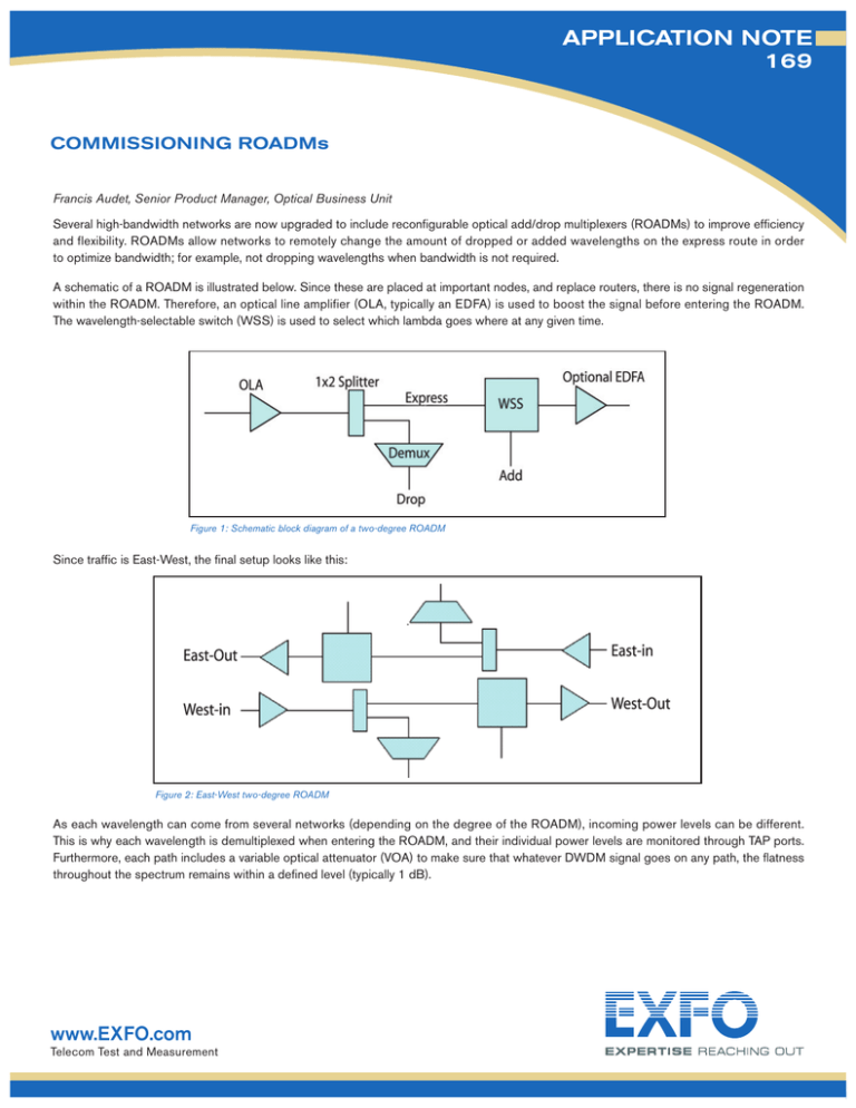
A schematic of a ROADM is illustrated below. Since these are placed at important nodes, and replace routers, there is no signal regeneration
within the ROADM. Therefore, an optical line amplifier (OLA, typically an EDFA) is used to boost the signal before entering the ROADM.
The wavelength-selectable switch (WSS) is used to select which lambda goes where at any given time.
Figure 1: Schematic block diagram of a two-degree ROADM
Since traffic is East-West, the final setup looks like this:
Figure 2: East-West two-degree ROADM
As each wavelength can come from several networks (depending on the degree of the ROADM), incoming power levels can be different.
This is why each wavelength is demultiplexed when entering the ROADM, and their individual power levels are monitored through TAP ports.
Furthermore, each path includes a variable optical attenuator (VOA) to make sure that whatever DWDM signal goes on any path, the flatness
throughout the spectrum remains within a defined level (typically 1 dB).
www.EXFO.com
Telecom Test and Measurement
APPLICATION NOTE 169
In this sense, commissioning the ROADM implies testing the OLA, the express route, as well as the drops and adds.
Testing the OLA Lightpath – The purpose of this is to test the OLA’s lightpath while the system is looped back upon itself (East-out
into West-in for example). This can be done by using an optical spectrum analyzer (such as EXFO’s FTB-5240) and a tunable laser source
(EXFO’s FLS-2600 for example). The OLA’s lightpath must be at least tested at the first and last DWDM channels (for example,
at DWDM channel 1 and DWDM channel 44 in a 44-channel system) since EDFA amplification curves are based on typical values;
nonetheless, testing at all channels is often preferred. A variable optical attenuator (like the FVA-60B) may be required to make sure that
the power entering the OLA is representative of what will be present during live traffic operation.
Testing the Wavelength-Selectable Switch – These tests are used to verify the optical signal level for any band, half-band or
express port pass-through paths. A tunable laser source (TLS) is plugged at the main input, and the OSA at the corresponding main output.
The loss per channel as the TLS sweeps should be within the published specifications of the ROADM. All ports should be tested: used,
unused as well as the express port. This is an extremely important test since, as mentioned above, the whole idea of the power meters and
variable attenuators in the ROADM is to ensure that all exiting wavelengths have similar power (within typically 1 dB). This means that
isolation loss that is too high on any of the express, add or drop ports, will automatically make all the other attenuators adjust, and power
levels of all other wavelengths will be lowered, thus losing usable power and potentially increasing OSNR.
Turning Up – When all losses and gains have been validated with the TLS, the final commissioning test prior to turn-up is to check the
impact of the ROADM on simulated live traffic, especially the impact on OSNR. At this point, the TLS is replaced by the transponders
of the system, and the OSNR should be within the acceptance level of the system manufacturer.
The standard entitled IEC 61280-2-9 Fiber Optic Communication Subsystem Test Procedures Part 2-9: Digital Systems Optical
Signal-to-Noise Ratio Measurement for Dense Wavelength-Division Multiplexed Systems defines optical signal-to-noise ratio (OSNR)
measurement as follows:
Ρ1+Ν1
Ν(λ1−Δλ)
Ν1
Ν(λ1+Δλ)
Figure 3: Graphical illustration of IEC 61280-2-9 Fiber Optic Communication
Subsystem Test Procedures Part 2-9: Digital Systems Optical Signal-to-Noise Ratio
Measurement for Dense Wavelength-Division Multiplexed Systems
APPLICATION NOTE 169
OSNR measurement is calculated as the average between the left and right OSNRs (which are themselves measured as the difference
in power between the peak power and the noise at half the distance between the peaks).
Unfortunately, the above description is not suitable for ROADMs. For example, let’s consider the wavelengths going through the express
route; since they can be remotely rerouted in any direction, they need to be demultiplexed. The wavelengths going through without being
dropped are then remultiplexed. Let’s examine the effects this has on the DWDM spectrum:
Figure 4a: Before the demultiplexer (demux)
Figure 4b: Individual wavelengths after the demux (the red
line represents the filter shape)
Figure 4c: After remultiplexing; the IEC-61280-2-9 measurement method is shown by the red arrow above, while the
real OSNR is shown in blue. OSAs that base their measurements on the IEC method make grave errors
The example illustrated above is a 100 GHz ROADM and a 10 Gbit/s transmitter. Even though the automatic OSNR measurement is wrong,
one can manually measure OSNR with visual markers. On a 50 GHz spacing device, the hump on either side of the peak visually disappears,
but it is still present as noise in the channel (known as in-band noise). The same remains true for the broader 40 Gbit/s transmissions.
www.EXFO.com
Telecom Test and Measurement
APPLICATION NOTE 169
Channel
Number
Position
(nm)
Peak Power
(dBm)
Ch.44
Ch.43
Ch. 35
Ch. 31
Ch. 30
Ch. 29
Ch. 28
Ch. 27
Ch. 26
Ch. 25
Ch. 24
Ch. 23
Ch. 22
Ch. 20
Ch. 16
Ch. 14
Ch. 13
Ch. 01
1529.546
1530.337
1536.605
1539.776
1540.558
1541.349
1542.146
1542.936
1543.734
1544.529
1545.321
1546.130
1546.918
1548.524
1551.714
1553.337
1554.134
1563.870
-27.31
-26.81
-25.86
-26.06
-26.19
-26.46
-26.72
-26.68
-26.09
-26.61
-26.27
-26.17
-26.13
-25.19
-24.28
-24.40
-24.13
-24.76
OSNR
IEC Standard
(dB)
30.1
30.0
30.8
30.9
31.0
31.5
15.0
31.2
30.7
31.2
14.5
14.4
27.7
28.1
31.1
29.7
29.8
30.9
EXFO’s
In-Band OSNR
(dB)
19.8
20.6
21.1
30.7
29.9
15.3
15.0
14.6
29.4
14.1
14.3
14.2
13.9
15.0
30.1
28.3
28.4
22.8
Table 1: OSNR results comparison between IEC standard and EXFO in-band measurements.
Lines in grey show channels where IEC approach would have resulted in a significant
measurement error.
Therefore, the chance of error is even greater since the odd shape cannot be seen. Furthermore, with ROADMs, signals can come from
different networks and be multiplexed (i.e., combined)—all these signals from different networks have different noise contributions. Therefore,
the interpolation of noise taken by measuring the left/right OSNRs becomes false and unreliable.
Measuring OSNR on ROADMs
The signal transmitting the data is polarized, while the noise, either amplified spontaneous emissions (ASE) or any other noise contributor,
is unpolarized. Adding a polarizer and a polarization controller in front of the OSA and adapting the data processing is one way to measure
in-band OSNR (removing the polarized signal results in in-band noise), but this method also adds unnecessary cost to the setup and
complexity to the test gear, making it a ROADM-dedicated OSA, which does not optimize the investment.
EXFO’s FTB-5240 and FTB-5240B OSAs have been designed with an internal polarization beam splitter (PBS) (US Patent 6,636,306,
originally mainly included to remove polarization-dependent loss (PDL) effects when analyzing dense wavelength-division multiplexing
(DWDM) signals). The internal design of the OSA, including the PBS, has the following appearance:
Figure 5. Visual representation of a bridged tap
www.EXFO.com
Telecom Test and Measurement
APPLICATION NOTE 169
By design, the polarization-dependent information is recognized by EXFO’s FTB-5240 and FTB-5240B OSAs. In addition to optimizing
the PDL, only an extra software feature is required to process the two polarizations to make them direct ROADM-ready OSAs. EXFO’s
FTB-5240/5240B OSAs that are already in service are just a software upgrade away from being ROADM-ready, which shows EXFO’s
commitment to the optimization of its products.
By separating two orthogonal polarizations, there is always a condition that shows the noise shoulders, which allows for direct measurement
of in-band noise.
Figure 6: Screen shot of in-band OSNR measurements taken with
EXFO’s FTB-5240B
With this in mind, EXFO developed a proprietary in-band measurement technique relying on polarization-diversity detection for ROADM-based
systems in which the OSNR values of peaks could not be measured correctly using the traditional IEC procedure involving
inter-channel noise estimation. The results show that the in-band OSNR is quite compatible with more elaborate manual testing procedures.
OSAs can be customized quite easily to monitor each ITU-based wavelength within the ROADM. Here is an example:
Channel Number
Position
EXFO: Out-of-Band OSNR (dB)
1
1550.109
-19.18
2
1550.528
-19.78
3
1550.919
-19.97
Table 2: Sample of customized ROADM channel measurements.
www.EXFO.com
Telecom Test and Measurement
APPLICATION NOTE 169
Network Characterization
The ROADM, as mentioned earlier, mainly replaced the O-E-O routers. Since the pulse reshaping capability of the router is gone, chromatic
dispersion and polarization mode dispersion (PMD) are not nulled at the ROADM site, and the all-optical link is now longer, as seen in these
two figures:
Figure 7: Before the ROADM, optical links were short
Figure 8: With ROADM in the network, the all-optical link can be increased multifold, requiring CD and PMD characterization
For chromatic dispersion, since wavelength can come and go to/from different networks, compensating at the receiver end proves extremely
complex, if not impossible. This is why ROADMs typically have integrated dispersion-compensating fibers (DCF) after the line amplifiers and
before the switch itself. This ensures that all wavelengths, whatever its origin and destination, is relatively well compensated for.
Longer links with several cascaded ROADM may require an additional tunable compensation at the receiving site to make up for the leftover
dispersion caused by the non-exactitude of the DCF and by the contribution of the ROADM itself. End-to-end testing may be required.
It is important to note that for end-to-end testing, the only way to perform this is to test through the EDFA (since they contribute to the total
CD), but by-passing the ROADM since testing for CD through it is not possible.
PMD causes a different challenge. PMD in fiber increases as the square root of the sum of the squares, because PMD in fiber is stochastic,
random. But ROADM are not fiber. The PMD in ROADM is deterministic and adds linearly. To illustrate the impact this could have, consider,
for example, that your system tolerance is 10 ps (typical for 10 Gbit/s SONET/SDH networks), and the ROADM has 1 ps of PMD (typical),
the tolerance for the fiber (including EDFA) is down to 9 ps. Networks with cascaded ROADMs see the fiber’s PMD tolerance decrease
proportionally. Again, this stresses the importance of testing every single link that will be part of the ROADM network, and end-to-end testing
may be required. It is important to note that for end-to-end testing, the only way to perform this is to test through the EDFA (since they
contribute to the total CD), but by-passing the ROADM since PMD cannot be tested through it.
Both the EXFO CD (FTB-5800) and PMD (FTB-5500B) analyzers are well suited for this job, as they can easily test through multiple
amplifiers with great speed and accuracy.
EXFO Corporate Headquarters > 400 Godin Avenue, Quebec City (Quebec) G1M 2K2 CANADA Tel.: 1 418 683-0211 Fax: 1 418 683-2170 info@EXFO.com
Toll-free: 1 800 663-3936 (USA and Canada) www.EXFO.com
EXFO America
EXFO Europe
EXFO Asia
EXFO China
Appnote169.2AN
3701 Plano Parkway, Suite 160
Omega Enterprise Park, Electron Way
151 Chin Swee Road, #03-29 Manhattan House
No. 88 Fuhua, First Road, Central Tower, Room 801
Futian District
Beijing New Century Hotel Office Tower, Room 1754-1755
No. 6 Southern Capital Gym Road
© 2008 EXFO Electro-Optical Engineering Inc. All rights reserved.
Plano, TX 75075 USA
Chandlers Ford, Hampshire S053 4SE ENGLAND
SINGAPORE 169876
Shenzhen 518048 P. R. CHINA
Tel.: 1 800 663-3936
Tel.: +44 2380 246810
Tel.: +65 6333 8241
Tel.: +86 (755) 8203 2300
Fax: 1 972 836-0164
Fax: +44 2380 246801
Fax: +65 6333 8242
Fax: +86 (755) 8203 2306
Beijing 100044 P. R. CHINA
Tel.: +86 (10) 6849 2738
Fax: +86 (10) 6849 2662
Printed in Canada 08/04

