ТУ "Стекло-3"
advertisement

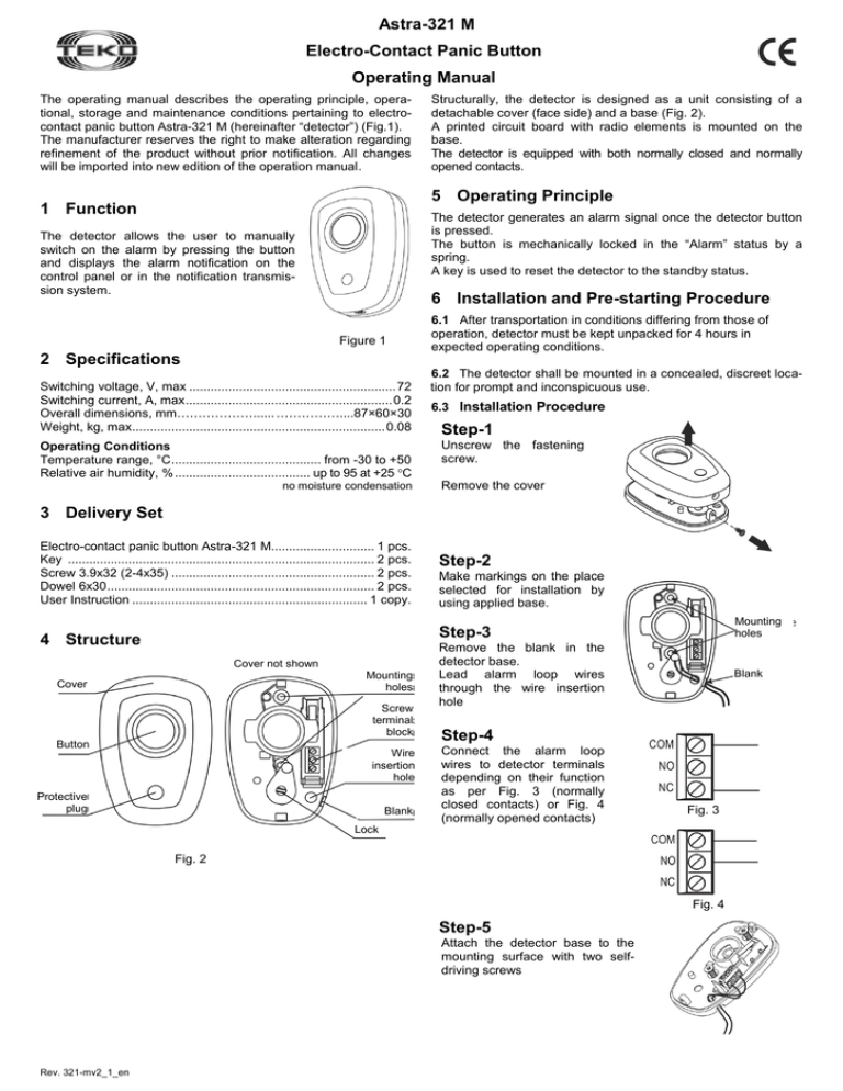
Astra-321 М Electro-Contact Panic Button Operating Manual The operating manual describes the operating principle, operational, storage and maintenance conditions pertaining to electrocontact panic button Astra-321 М (hereinafter “detector”) (Fig.1). The manufacturer reserves the right to make alteration regarding refinement of the product without prior notification. All changes will be imported into new edition of the operation manual. Structurally, the detector is designed as a unit consisting of a detachable cover (face side) and a base (Fig. 2). A printed circuit board with radio elements is mounted on the base. The detector is equipped with both normally closed and normally opened contacts. 5 Operating Principle 1 Function The detector generates an alarm signal once the detector button is pressed. The button is mechanically locked in the “Alarm” status by a spring. A key is used to reset the detector to the standby status. The detector allows the user to manually switch on the alarm by pressing the button and displays the alarm notification on the control panel or in the notification transmission system. 6 Installation and Pre-starting Procedure Figure 1 2 Specifications Switching voltage, V, max .......................................................... 72 Switching current, A, max .......................................................... 0.2 Overall dimensions, mm………………...... ……………....87×60×30 Weight, kg, max ....................................................................... 0.08 Operating Conditions Temperature range, °С .......................................... from -30 to +50 Relative air humidity, % ...................................... up to 95 at +25 °С no moisture condensation 6.1 After transportation in conditions differing from those of operation, detector must be kept unpacked for 4 hours in expected operating conditions. 6.2 The detector shall be mounted in a concealed, discreet location for prompt and inconspicuous use. 6.3 Installation Procedure Step-1 Unscrew the fastening screw. Remove the cover 3 Delivery Set Electro-contact panic button Astra-321 М............................. 1 pcs. Key ...................................................................................... 2 pcs. Screw 3.9x32 (2-4х35) ......................................................... 2 pcs. Dowel 6х30 ........................................................................... 2 pcs. User Instruction .................................................................. 1 copy. Step-2 Make markings on the place selected for installation by using applied base. Mounting holes Step-3 4 Structure Cover not shown Mounting holes Cover Screw terminal block Button Wire insertion hole Protective plug Blank Remove the blank in the detector base. Lead alarm loop wires through the wire insertion hole Blank Step-4 Connect the alarm loop wires to detector terminals depending on their function as per Fig. 3 (normally closed contacts) or Fig. 4 (normally opened contacts) Fig. 3 Lock Fig. 2 Fig. 4 Step-5 Attach the detector base to the mounting surface with two selfdriving screws Rev. 321-mv2_1_en Step-6 8 Replace the cover and fasten it with the fastening screw This product is in conformity with the provisions of: EMC 89/336/EEC EN 61000-6-3:2005 Electromagnetic compatibility (EMC) - Part 63: Generic standards - Emission standard for residential, commercial and light-industrial environments EN 50130-4/1995 + A1:1998 + A2:2003 + Corrig. 2003 Alarm systems - Part 4: Electromagnetic compatibility - Product family standard: Immunity requirements for components of fire, intruder and social alarm systems EN 60950-1: 2001+A11:2004+Corrig.2004 Safety of information technology equipment. Step-7 Check detector operability by pressing the button. The button shall remain locked in pressed position 9 Recycling The detector is not a danger to life, human health and the environment. On expiry of its lifetime recycling is done without taking special measures to protect the environment. Step-8 To restore the detector to the standby status: - remove the protective plug; - insert the key into the keyhole and rotate counterclockwise until the button is unlocked; - remove the key; - mount the protective plug back into its position 10 Manufacturer Warranties 10.1 Quality Management System meets provisions of ISO 90012011. 10.2 The manufacturer guarantees the compliance of the detector with technical requirements provided the transportation, storage, mounting and operating rules and requirements are observed by user. 10.3 The storage warranty period is 2 years and 6 months from the date of manufacture. 10.4 The operation warranty period is 2 years from the date of putting into operation but no longer than 2 years 6 months from the date of manufacturing. 10.5 The manufacturer shall repair or replace a faulty detector during the warranty period. 10.6 The warranty becomes void if: - the user does not follow guidelines of the operating manual; - the detector is mechanically damaged; - the detector is repaired by a party other than the Manufacturer. 10.7 The warranty covers the detector only. All equipment manufactured by other parties and used with the detector is covered by its respective warranty. The manufacturer bears no responsibility for death, injury, property damage or other incidental or premeditated loss based on the user's statement that the button has failed to implement its functions. 6.4 To provide for reliable operation of the alarm system it is recommended to test the detector at least once a week. 7 EC Conformity Declarations Labeling The following data are shown on the label glued to the body: - manufacturer trademark; - detector abbreviated name or designation; - month and year of manufacture (last two digits); - conformity mark (if the conformity certificate is available). Sales: Controlex GmbH Warranty service and technical support: ТЕКО-TD Philosophenweg 31-33 47051 Duisburg, Germany Phone: +49 (0) 203 / 393 91 188 Fax: +49 (0) 203 / 393 91 189 GSM: +49 (0) 178 / 218 48 22 E-mail: info@controlex.eu Web: www.controlex.eu Prospekt Pobedy str. 19 420138 Kazan, Russia Phone: +7 (843) 261-55-75 Fax: +7 (843) 261-58-08 E-mail: info@teko.biz support@teko.biz Web: www.teko.biz Made in Russia 2 Rev. 321-mv2_1_en


