W W W . M K S I N S T . C O M
Flow Solutions
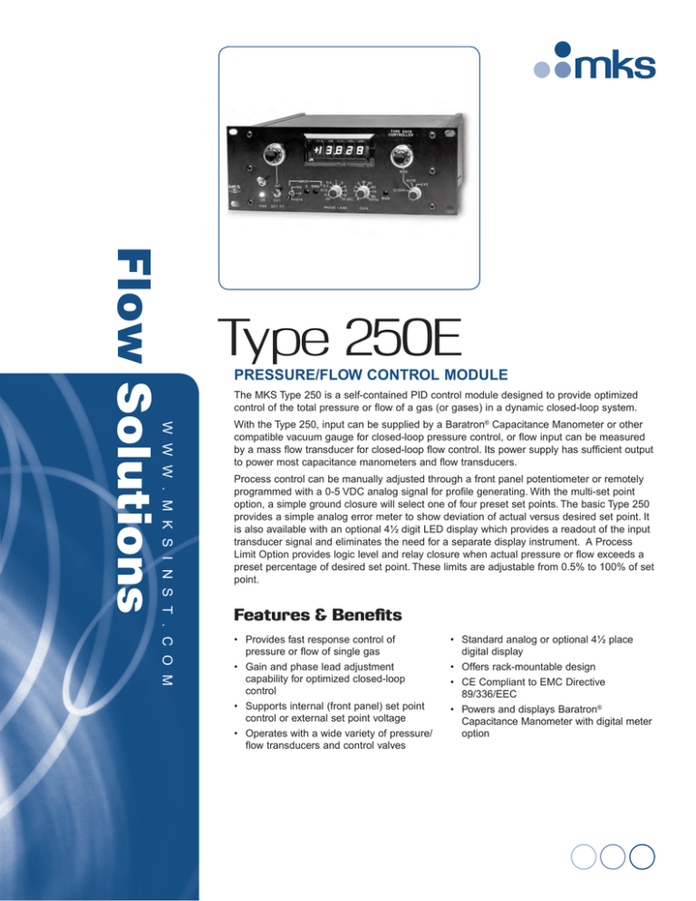
Type 250E
PRESSURE/FLOW CONTROL MODULE
The MKS Type 250 is a self-contained PID control module designed to provide optimized
control of the total pressure or flow of a gas (or gases) in a dynamic closed-loop system.
With the Type 250, input can be supplied by a Baratron® Capacitance Manometer or other
compatible vacuum gauge for closed-loop pressure control, or flow input can be measured
by a mass flow transducer for closed-loop flow control. Its power supply has sufficient output
to power most capacitance manometers and flow transducers.
Process control can be manually adjusted through a front panel potentiometer or remotely
programmed with a 0-5 VDC analog signal for profile generating. With the multi-set point
option, a simple ground closure will select one of four preset set points. The basic Type 250
provides a simple analog error meter to show deviation of actual versus desired set point. It
is also available with an optional 4½ digit LED display which provides a readout of the input
transducer signal and eliminates the need for a separate display instrument. A Process
Limit Option provides logic level and relay closure when actual pressure or flow exceeds a
preset percentage of desired set point. These limits are adjustable from 0.5% to 100% of set
point.
Features & Benefits
• Provides fast response control of pressure or flow of single gas
• Gain and phase lead adjustment capability for optimized closed-loop control
• Supports internal (front panel) set point control or external set point voltage
• Operates with a wide variety of pressure/
flow transducers and control valves
• Standard analog or optional 4½ place digital display
• Offers rack-mountable design
• CE Compliant to EMC Directive 89/336/EEC
• Powers and displays Baratron® Capacitance Manometer with digital meter option
Application Schematics
A pressure/flow control system consists of three basic
parts: 1) a process sensor, 2) a PID controller, and 3) a
control element. In the simplest single-gas control system
(Figure 1), a pressure transducer or mass flow meter
measures the process pressure or gas inlet flow rate. The
Type 250 PID controller compares the measured pressure
or flow to the desired set point and adjusts the gas flow
control valve as necessary to achieve set point.
For pressure control with multiple gases, the Type 250
can be used as the master controller to several mass flow
controllers (Figure 2). In this configuration, multiple MFCs
are slaved to the output of the Type 250, which adjusts the
total flow to achieve the desired pressure, while the flow
electronics maintains the desired gas ratio/mixture.
Gas Supply
Proportioning
Control Valve
Mass Flow Meter
Process
Chamber
Power
250
Set Point Input
Baratron
Pressure
Transducer
Vacuum
Pressure/Flow Output 0-5 VDC /
0-10 VDC To Readout Data
Logger
Figure 1 —
Upstream pressure or flow control system
Power
Many processes require a constant total flow, as well as
ratio of the inlet gases, yet still require a constant pressure.
In this case (Figure 3), the inlet gases are controlled
independently of the pressure control. The Type 250 is
used to operate a valve located in the gas ballast line
located between the process chamber and pump. With the
upstream gas inlet flow rate (total and ratio) held constant
by the MFCs and the electronics, the Type 250 adjusts the
gas ballast flow to achieve the desired pressure set point.
Type 247
G1
G2
G3
Pressure Control
Signal (PCS)
G4
Compatible Control Valves
MKS control valves are solenoid-actuated proportioning
control valves designed for precise control of gaseous
flows in the range from 0.1 sccm to 200 slm. The MKS
Type 250 control module is compatible with Types 148,
154 and 248 control valves.
The 148 valve is a metal-sealed design for high purity
applications and for the delivery of hazardous gases
where minute leakage to atmosphere cannot be tolerated.
It controls flows in the range of 10 to 30,000 sccm.
Process
Chamber
250
Baratron
Pressure
Transducer
Vacuum
Power
Figure 2 —
Upstream pressure control system with four-gas ratio
G1
The Type 154 valve is designed for flow rates from 20
to 200 slm and uses a patented balanced-forces control
valve. Unlike pilot valves and other magnetically-actuated
solenoid valves, the 154 enables fast response to set point
changes without oscillations over a wide range of inlet
pressures. Because the 154 requires higher drive current,
the 250E must be modified for this. Use with the 154
should be noted when placing orders.
The Type 248 is an elastomer sealed, general purpose
valve for applications from 10 sccm to 50,000 sccm.
Set Point
G2
G3
G4
Type 247
Baratron Pressure
Transducer
Process
Chamber
250
Type 248
Valve
Vacuum
Pump
Set Point
Power
Gas Ballast Supply
Figure 3 —
Downstream pressure control with up to four independent gases using a gas
ballast technique
Specifications
Control Accuracy
0.25% of Full Scale
0.1, 1 or 10 VDC selectable on front panel
Control Loop Tuning
Phase lead
0.05 sec to 10 sec
Gain
0.2% to 100%
Compatible Control Valves
Proportioning
Types 148, 248, and 154 (A special version of the Type 250 is required to drive the Type 154 control valve. Contact Applications Engineering.)
Power Input
115/230 VAC, 50-60 Hz, 50 Watts Power Output
±15 VDC @ 250 mA (to power input transducers)
Signal Input (from transducer)
0 to ±0.1, 1 or 10 VDC
Input Impedance
>200K W
Display
Standard
Optional
analog error meter
4½ digit LED input signal display
Signal Outputs
Input transducer signal
Pressure control signal
0-5, 10 VDC into >10K Ω load
0-10 VDC
Remote Control Analog set point input
0 to 5 VDC into 40K Ω load
Multi-set point select (option)
ground closure to select (one or four set points)
Valve close or auto operation
ground closure to select
Process limits (option)
logic level and relay closure adjustable 0.5 to 100% of set point
Operating Temperature Range
0°C to 40°C
Size
Millimeters
Inches
241W x 89H x 229D
9.5”W x 3.5”H x 9.0”D
Mounting
bench-top or rack-mount
Electromagnetic Compatibility
Fully compliant to EMC Directive 89/336/EEC when used with an overall metal braided shielded cable, properly grounded at both ends
Product Safety
Fully compliant to Low Voltage Directive 72/23/EEC
Compatible Control Valves
Type 154
Full Scale Flow Range
20 to 200 slm
Types 148J (metal seal) Type 248 (elastomer seal)*
10 to 30,000 sccm
10 to 50,000 sccm
Minimum
0.1% of F.S.
<2% F.S. Controllable Flow
0.2% F.S. (<100 sccm)
0.1% F.S. (100 to 10,000 sccm)
<2% F.S. (>10,000 sccm)
Closed Conductance Leakage <0.1% of F.S.
<1% F.S. (15 psid to atm)
<1 × 10⁻⁵ scc/sec He (up to 10,000 sccm)
<1% F.S. (>10,000 sccm)
Wetted Materials
Standard
316 S.S., Nickel, Viton®
316 S.S., Nickel, Teflon
316 S.S., Viton
Optional Buna-N, Kalrez, Neoprene® Buna-N, Kalrez, Neoprene
Fittings Standard
½” Swagelok®
4 VCR® male
¼” Swagelok Optional
8 VCR or 8 VCO male
4 VCR or 4 VCO male
Operating Temperature Range
-10°C to +60°C
Electromagnetic Compatibility
15°C to +50°C
(bakeable to 150°C)
-10°C to +60°
Fully CE compliant to EMC Directive 2004/108/EC when used with an overall metal braided shielded cable properly grounded at both ends (the 154 valve requires a special modification for CE compliance)
* For 20,000 and 50,000 sccm, maximum 248 operating pressure drop is 15 psig to atmosphere.
Ordering Information
8.00
(203)
9.0
(22 0
9)
3.38
(86)
0.23
(6)
3.00
(76)
3.47
(88)
8.88
(226)
9.47
(241)
Ordering Code Example: 250E1APLO
Code
Type 250 Pressure/Flow Control Module
250E
Number of Set Points
Standard: one set point
1
Optional: four set points
4
Display Options
Standard: Analog Error Meter
A
Optional: 4½ Place Digital Display
D
PLO Process Limit
PLO
Note: Use with the 154 should be noted when placing orders.
Configuration
250E
1
A
Note: Allow 2.5" (63 mm) clearance behind rear panel for connectors/cables.
Dimensional Drawing —
Note: Unless otherwise specified, dimensions
are nominal values in inches (mm referenced).
Valve Dimensions
Dimensions (nominal)
A
B
C
Width
Valve Type
(in)
(mm)
(in)
(mm)
(in)
(mm)
(in)
148J
4 VCR
3.36
85.3
4.04
102.6
0.5
12.7
1.5
(mm)
38.1
248A
4 VCR
4 VCO
1/4'' Swagelok
3.37
3.05
2.76
85.6
77.5
70.1
3.38
85.9
0.5
12.7
1.5
38.1
154A
8 VCR
8 VCO
1/2'' Swagelok
4.62
4.31
4.25
117.3
109.5
108.0
4.5
114.3
0.75
19.1
1.53
38.9
Dimensional Drawing —
Note: Unless otherwise specified, dimensions
are nominal values in inches (mm referenced).
250 - 11/15
© 2006 MKS Instruments, Inc.
All rights reserved.
Ordering Code Example: 148JA11CR1M
Code
Configuration
148J
Type 148J Control Valve
148JA
Full Scale Range
10 sccm
11C
20 sccm
21C
50 sccm
51C
100 sccm
12C
200 sccm
22C
500 sccm
52C
11C
1000 sccm
13C
2000 sccm
23C
5000 sccm
53C
10,000 sccm
14C
20,000 sccm
24C
30,000 sccm 34C
Fittings
Swagelok 4 VCR
R
R
Valve Normally closed
1
1
Valve Seal Material
Metal
M
M
Ordering Code Example: 0248A00050SV
Types 154 & 248 Elastomer-Sealed Control Valves
Type 0154
Type 0248
Full Scale Range (sccm of N2)
10 sccm
20 sccm
50 sccm
100 sccm
200 sccm
500 sccm
1000 sccm
2000 sccm
5000 sccm
10,000 sccm
20,000 sccm
50,000 sccm 200 slm
Fittings
½” Swagelok
8 VCR male
8 VCO male
¼” Swagelok 4 VCR male
4 VCO male
Seals
Viton
Buna-N
Kalrez
Neoprene
Code
0154A
0248A
Configuration
0248A
00010
00020
00050
00100
00200
00500
248 only
01000
00050
02000
05000
10000
20000
50000
200L (154 only)
S (Type 154 only)
R (Type 154 only)
G (Type 154 only)
S
S (Type 248 only)
R (Type 248 only)
G (Type 248 only)
V
B
V
K
N
MKS Instruments, Inc.
Global Headquarters
MKS Instruments, Inc.
Flow Solutions
2 Tech Drive, Suite 201
Andover, MA 01810
Six Shattuck Road
Andover, MA 01810
Tel:978.645.5500
Tel: 800.227.8766 (in U.S.A.)
Web:www.mksinst.com
Tel:978.975.2350
MKS products provided subject to the US Export Regulations. Diversion or transfer contrary to US law is prohibited.
Specifications are subject to change without notice. mksinst™ is a trademark and Baratron® and Mass-Flo® are registered
trademarks of MKS Instruments, Inc., Andover, MA. Viton®, Neoprene® and Kalrez® are registered trademarks of E.I. Dupont
Co., Inc., Wilmington, DE. Swagelok®, VCR® and VCO® are registered trademarks of Swagelok Marketing Co., Solon, OH.


