AN0-39 Speed IM testing
advertisement
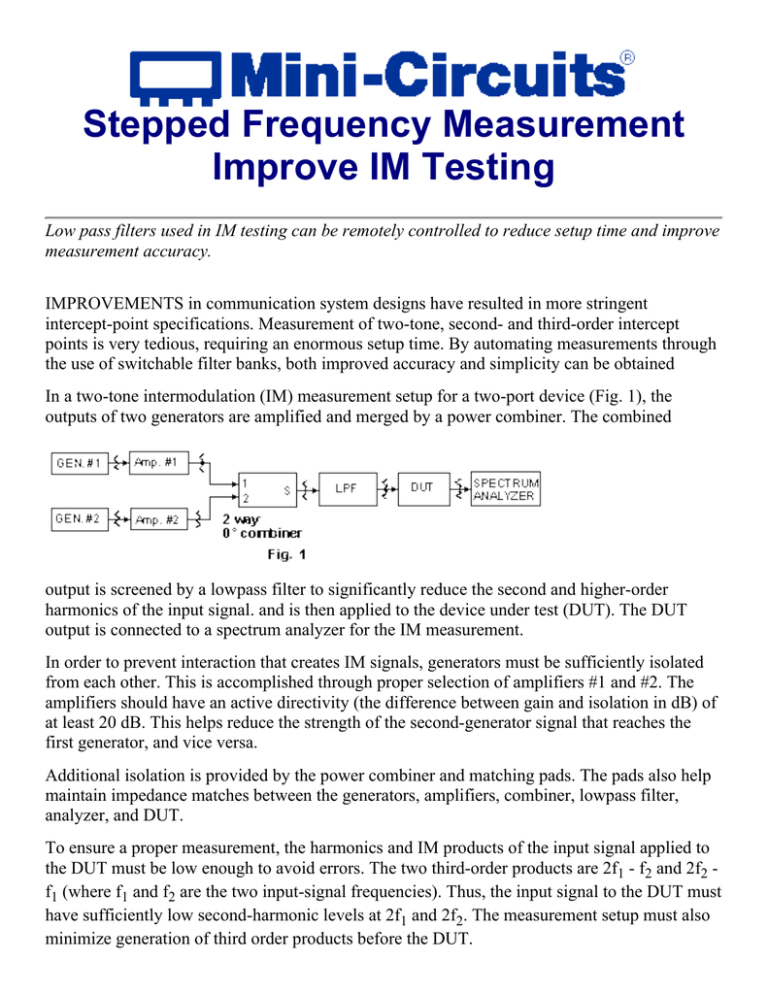
Stepped Frequency Measurement Improve IM Testing Low pass filters used in IM testing can be remotely controlled to reduce setup time and improve measurement accuracy. IMPROVEMENTS in communication system designs have resulted in more stringent intercept-point specifications. Measurement of two-tone, second- and third-order intercept points is very tedious, requiring an enormous setup time. By automating measurements through the use of switchable filter banks, both improved accuracy and simplicity can be obtained In a two-tone intermodulation (IM) measurement setup for a two-port device (Fig. 1), the outputs of two generators are amplified and merged by a power combiner. The combined output is screened by a lowpass filter to significantly reduce the second and higher-order harmonics of the input signal. and is then applied to the device under test (DUT). The DUT output is connected to a spectrum analyzer for the IM measurement. In order to prevent interaction that creates IM signals, generators must be sufficiently isolated from each other. This is accomplished through proper selection of amplifiers #1 and #2. The amplifiers should have an active directivity (the difference between gain and isolation in dB) of at least 20 dB. This helps reduce the strength of the second-generator signal that reaches the first generator, and vice versa. Additional isolation is provided by the power combiner and matching pads. The pads also help maintain impedance matches between the generators, amplifiers, combiner, lowpass filter, analyzer, and DUT. To ensure a proper measurement, the harmonics and IM products of the input signal applied to the DUT must be low enough to avoid errors. The two third-order products are 2f1 - f2 and 2f2 f1 (where f1 and f2 are the two input-signal frequencies). Thus, the input signal to the DUT must have sufficiently low second-harmonic levels at 2f1 and 2f2. The measurement setup must also minimize generation of third order products before the DUT. An example (Fig. 2) using an amplifier as a DUT illustrates the methods of computing acceptable measurement system IM levels. The amplifier has a third-order intercept point (IP3) of 50 dBm and a l-dB Compression point of 29 dBm. IM measurements are made at a 15-dBm output-power level. The IM levels at the amplifier output are: IP3 (in dBm) = Pout + A/2 (1a) 50 = 15 + A/2 (1b) A = 70dB (1c) where: Pout= output power, and A = third-order IM level below the carrier. In order to reduce the measurement error, the IM level at the amplifier input must be at least 80 dB below the carrier (10 dB below A). The second harmonics of the input signals should also be at least 80 dB down. Second-order products are at 2f1, 2f2, and f1 + f2. If the amplifier has a second-order intercept point (IP2) of 70 dBm, then: IP2 = Pout + B (2a) 70 = 15 + B (2b) B = 55dB (2c) where: B = second-harmonic or 2nd-order IM level below the carrier. Thus, the second-harmonic level of the DUT input should be at least 65 dB (B + 10) for accurate IP2 measurement. Since second-and third-order measurements are done simultaneously, the second-harmonic levels should satisfy the requirements of both equations; i.e., they should be at least 80 dB below the carrier. Accurate measurement of second- and third-order intercept points involves gauging the input-signal IM products and harmonics, and output IM products to determine if the input levels are acceptable. This must be done for each DUT at every measurement frequency. Another important aspect of IM measurement is ensuring that the input-signal strength to the analyzer is not too high, since the analyzer itself can generate IM and produce erroneous readings. In order to detect this IM distortion, the analyzer attenuation is increased by 10 dB. If the IM level with respect to the main signal (fl and f2) does not change, the IM is being caused by the DUT. If the level does change, the attenuation should be increased until the IM level is not affected. All these precautions must be exercised for each measurement, and if done manually, will be very time-consuming and tedious. Wideband measurement of the IM is done by conducting IM tests at several discrete frequencies in the band of interest. One way to automate the test setup is to use an electronically tuned filter that can be remotely controlled. However, such filters are not readily available at RF frequencies. Another approach is to use an arrangement of fixed frequency lowpass filters and then electronically select the proper filter (Fig. 3). This arrangement of filters replaces the single lowpass filter used in the basic IM test setup. Any number of filters can be utilized in the arrangement The frequency of the input signal determines the filter to be selected. This choice is done via computer, and all measurements are repeated to confirm their accuracy. Once output IM measurements are completed, results are compared to the input signal IM and harmonic levels. If sufficient margins exist, the results are validated. To further enhance the usefulness of this setup, test specifications are built into the computer. After completion of the measurements, results are compared to the test specification, with pass/fail status indicated on the computer screen. This method reduces test time substantially (ranging from one third to one fifth of the manual test time) and improves measurement accuracy. Last Updaetd: 12/17/1999
