Encoder–Decoder Design for Feedback Control over the
advertisement
Encoder–Decoder Design for Feedback Control over the Binary
Symmetric Channel
Lei Bao, Mikael Skoglund and Karl Henrik Johansson
School of Electrical Engineering, Royal Institute of Technology, Stockholm, Sweden
Email: lei.bao@ee.kth.se, skoglund@ee.kth.se, kallej@ee.kth.se
PSfrag replacements
Abstract— Encoder–decoder design is considered for a closedloop scalar control system with feedback transmitted over a
binary symmetric channel. We propose an iterative procedure
which can jointly optimize adaptive encoder–decoder pairs for a
certainty equivalence controller. The goal is to minimize a design
criterion, in particular, the linear quadratic (LQ) cost function
over a finite horizon. The algorithm leads to a practically feasible
design of time-varying non-uniform encoding and decoding. Numerical results demonstrate the promising performance obtained
by employing the proposed iterative optimization algorithm.
I. INTRODUCTION
In recent years, the demand for sharing resources efficiently
in large networked systems has been continuously increasing.
However, in many situations, there is a challenging conflict
between the amount of transmitted data and the response time.
In particular for emerging control applications, limits imposed
on available signaling bandwidth from communication channels, can severely restrict closed-loop performance and even
destabilize the system. Networked control based on limited
sensor and actuator information has therefore attracted much
attention during the past decade, e.g., [1], [2], [3], [4], [5], and
the references therein.
Up to now, the existing work on control with limited information has mainly developed theory for error-free feedback
systems. Examples of previous works investigating transmission over noisy channels include [5], [6]. The main contribution of the present paper is a practical synthesis technique
for joint optimization of the encoder and the decoder for
observation feedback over a noisy channel. In particular, we
consider the binary symmetric channel (BSC). The corresponding scenario was considered for noiseless channels in our
previous work [7]. In most practical situations, especially in
a wireless environment, a noiseless assumption is unrealistic,
which motivates this extension to feedback signals corrupted
by channel errors. We have derived optimal encoder–decoder
pairs for a given probability density function (pdf) of the plant
initial state and a given cross-over probability ε . We show that
this problem is numerically solvable and it leads to channel
optimized encoder–decoder pairs that provide better control
performance.
The paper is organized as follows. A motivating example is
presented in Sec. II. Sec. III defines the control system with
encoder, decoder, and communication channel. The problem
statement, which concerns a linear quadratic objective over
finite horizon, is presented in Sec. IV. The joint encoder–
decoder design and the training procedure based on dynamic
Plant
Controller
sensor sensor
sensor
Wireless
Channel
sensor sensor
Actuator
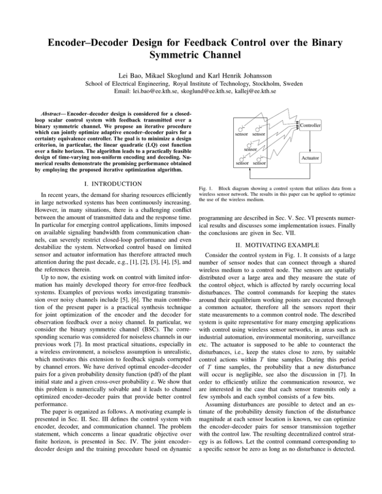
Fig. 1. Block diagram showing a control system that utilizes data from a
wireless sensor network. The results in this paper can be applied to optimize
the use of the wireless medium.
programming are described in Sec. V. Sec. VI presents numerical results and discusses some implementation issues. Finally
the conclusions are given in Sec. VII.
II. MOTIVATING EXAMPLE
Consider the control system in Fig. 1. It consists of a large
number of sensor nodes that can connect through a shared
wireless medium to a control node. The sensors are spatially
distributed over a large area and they measure the state of
the control object, which is affected by rarely occurring local
disturbances. The control commands for keeping the states
around their equilibrium working points are executed through
a common actuator, therefore all the sensors report their
state measurements to a common control node. The described
system is quite representative for many emerging applications
with control using wireless sensor networks, in areas such as
industrial automation, environmental monitoring, surveillance
etc. The actuator is supposed to be able to counteract the
disturbances, i.e., keep the states close to zero, by suitable
control actions within T time samples. During this period
of T time samples, the probability that a new disturbance
will occur is negligible, see also the discussion in [7]. In
order to efficiently utilize the communication resource, we
are interested in the case that each sensor transmits only a
few symbols and each symbol consists of a few bits.
Assuming disturbances are possible to detect and an estimate of the probability density function of the disturbance
magnitude at each sensor location is known, we can optimize
the encoder–decoder pairs for sensor transmission together
with the control law. The resulting decentralized control strategy is as follows. Let the control command corresponding to
a specific sensor be zero as long as no disturbance is detected.
vt
wt
x0
Plant
et
yt
ht (xt )
Encoder
c(it )
Channel
Estimator
...
Controller
ut
Decoder
dt
Fig. 2.
c( jt )
Feedback control system with channel constraints.
When the sensor detects a disturbance, the sensor reading is
encoded and transmitted to the controller node. The message
is decoded at the controller node and a control command is
derived and actuated to counteract the specific disturbance
acting on the transmitting sensor. The controller and the
encoder–decoder pairs are designed based on a finite-horizon
linear quadratic criterion. A partial solution is therefore to
solve the linear quadratic problem with uncertainty both in
the initial condition and the information transmission. In this
paper, a class of time-varying non-uniform encoder–decoders
is derived, which together with a simple state feedback for a
control system is suitable to handle this situation.
causally utilizes full information, i.e., Dt = {jt0 , ut−1
0 }. The
decoder is then a deterministic mapping
dt = gt (jt0 , ut−1
0 )
(4)
ut = zt (dt0 , ut−1
0 )
(5)
x̂s|t = E{xs |jt0 , ut0 }
(6)
from Dt to R.
Also, let Ct , in particular Ct = {dt0 , ut−1
0 }, denote the (full)
information available at the controller. The controller is then
defined by the mapping
from Ct to R. We also define
to be the minimum mean square error estimator of the state
xs , for s ≤ t, based on jt0 and ut0 . Finally, note that even
if all variables are not available at all nodes in the system,
we assume that the functionalities of the encoder, decoder,
controller and state-estimator are known at all nodes.
IV. PROBLEM STATEMENT
Let us focus on a special instance of the system in Fig. 2,
namely a stable scalar linear time-invariant plant, in absence
of process noise vt and observation noise et . Perfect state
observations are available at the encoder, yt = xt and Et =
III. PRELIMINARIES
t−1 t−1
{xt0 , it−1
0 , u0 , j0 }. The index it is transmitted via a BSC,
Consider the control system with a communication channel and the initial state x0 is unknown, with known pdf p(x0 ),
depicted in Fig. 2. In this section we describe a general
PSfrag version
replacements
xt+1 = a xt + ut ,
yt = xt ,
|a| < 1.
(7)
of the system. Let xba = {xa , . . . , xb } denote the evolution of a
R
discrete-time signal xt from t = a to t = b. The plant is given Let c(it ) ∈ {0, 1} be a binary codeword of length R repreby the scalar system
senting the encoder output it ∈ IL . The mapping between it
and c(it ) is referred to as the index assignment (IA), cf. [8].
xt+1 = θt (xtt−Mx , ut ) + vt ,
For
example, the natural binary code assigns the natural binary
(1)
yt = ht (xt ) + et ,
representation
of an integer i to the codeword ci . At time t,
qj1 =0,2
0
the
relation
between
the it and c(it ) is then
which has a memory of order Mx . xt , ut , yt ∈ R are the state,
the control, and the measurement, respectively. The process
it = k ⇔ c(it ) = ck , k ∈ IL .
disturbance and the measurement noise are represented by vt q
jIn
0 =2a similar way, c( jt ) denotes the received binary codeword,
and et , respectively.
Let Et denote the set of “information” available at the where jt ∈ IL is the received index.
encoder, at time t, that is, the set of variables with values
q j0 =0 qj1 =0,0 . . .
q j0 =0 qj10 =0,0 . . .
Codebook q j0 =1 qj010 =0,1 . . .
Codebook q j0 =1 qj10 =0,1 . . .
known to the encoder. In particular, we consider an encoder
.
.
.
.
.
.
.
.
.
...
... ...
BCB
that causally utilizes full information, in the sense Et =
t−1 t−1
{yt0 , it−1
0 , u0 , j0 }. The encoder is then a mapping from
xt
c(it )
dt
c( jt )
Et to a discrete set of symbols. We take each symbol to
Channel
Encoder
Decoder
be represented by an integer index. At time t, the index is
it ∈ IL = {0, 1, . . . , L − 1}, where L = 2R with R denoting the
rate of the transmission, in bits per state measurement. Hence,
Fig. 3. There is a common codebook at the encoder and the decoder.
the encoder is described by the mapping
A BSC is described by the cross-over probability ε =
t−1 t−1
p(0|1)
= p(1|0). Assuming independent transmission of each
it = ft (yt0 , it−1
,
j
,
u
).
(2)
0
0
0
bit, the conditional probability of a codeword p(c j |ci ) is a
Let the discrete channel have input variable it and output jt ,
function of ε ,
with one channel use defined by
(8)
p(c j |ci ) = (1 − ε )R−dH (ci ,c j ) ε dH (ci ,c j ) ,
jt = kt (itt−Mc ),
(3)
where dH (ci , c j ) is the Hamming distance between the binary
where kt : ILMc +1 → IL is a random mapping, and Mc ≥ 0 codewords ci and c j . Moreover, we assume the encoder and
indicates (potential) channel memory.
the decoder have access to the same codebook (Fig. 3), which
T −1
, with j indicating
At the receiver, we denote the information available at consists of reconstruction points {qjt }t=0
0
the decoder by Dt ; in particular, we consider a decoder that the received index.
A. Performance Measure
The goal of this paper is to solve an integrated encoder–
decoder design and optimal control problem for the system
in (7). The performance measure is the linear quadratic cost
function with horizon T ,
)
(
T −1 (9)
JT = E xT2 + ∑ xt2 + ρ ut2 ,
t=0
where ρ ≥ 0 specifies the relative weight of control ut .
B. Encoder–Decoder Structure
Intuitively, for control applications with strict delay constraints and bandwidth limitations, joint designs can improve
upon traditional approaches. In this section, we present a
design method, suitable for short codewords, accomplishing
source compression and channel protection simultaneously,
in a similar fashion to traditional channel optimized source
coding techniques, e.g., [8].
The presence of a noisy channel raises an encoder–decoder
synchronization problem. In case of noise-free feedback, i.e.,
it0 = jt0 , there is no uncertainty in the information the encoder
intends to convey to the decoder. That is to say, the encoder
and the decoder have identical information about previous
events. Such synchronization between the encoder and the
decoder is eliminated when the channel produces transmission
errors, since the encoder can not make error-free prediction
of what index jt the decoder will receive in advance. Even
worse, the decoder has completely lost the ability to perfectly
deduce the transmitted indices it0 by examining received values
for jt−1
0 . However, since we assume a reliable actuation link,
the encoder can in fact calculate jt−1 based on knowing xt .
can define common information about
Thus, the sequence jt−1
0
previous events, referred here to as common memory.
A fundamental problem in system design involving noisy
channels is how to handle the impairment caused by channel
errors. The two basic strategies are either to prevent in advance
or handle errors after they have appeared. In this paper, we
choose the first strategy, that is designing the reconstruction
points taking the probability of bit errors into account. Our
strategy is realized by letting both encoding and decoding
be based on the received indices jt−1
0 , cf. Fig. 3. Encoder–
decoder design is then essentially equivalent to the problem
of constructing an optimal strategy for the encoder to successively inform the decoder about the initial state, x0 . Note
that the encoder knows ut0 , based on jt0 . Moreover, xt1 can be
computed from (x0 , ut−1
0 ). Hence we assume, from now on,
that it is generated as
it = ft (x0 , jt−1
0 ),
t = 0, . . . , T − 1,
(10)
based on x0 and the past indices jt−1
0 .
At the receiver, ut0 can be computed from jt0 , hence in the
following the assumed decoder mapping will be
dt = gt (jt0 ),
t = 0, . . . , T − 1.
(11)
Finally, the optimal state estimator, based on Dt is
x̂s|t = E{xs |jt0 },
t = 0, . . . , T − 1, s ≤ t.
(12)
As will be explained later, the decoder mapping will be
specialized to dt = x̂t|t , so x̂t|t will be utilized by the controller
to produce the control output ut .
V. ENCODER–DECODER DESIGN
This section presents the main result of the paper. After discussing certainty equivalence and encoder–decoder mappings,
we present an overall training algorithm.
A. Certainty Equivalence
In general, optimal performance is achievable only when
the coding and the control are designed jointly. There are
examples, however, when the separation principle applies to
subclasses of the problem considered in this paper. The socalled certainty equivalence controller remains optimal when
the estimation errors are independent of previous control
commands [9].
To apply the certainty equivalence principle to our problem,
in designing the optimal decoder {gt }T0 −1 and controller
{zt }T0 −1 , for fixed encoder { ft }T0 −1 , with it = ft (x0 , jt−1
0 ),
we note that the necessary and sufficient condition in [9]
corresponds to the requirement that the average estimation
error
E{(x0 − x̂0|t )2 }, t = 0, . . . , T − 1,
(13)
is not a function of us0 , for s = 0, . . . ,t − 1, for any sequence us0
of controls. It is quite straightforward to verify that this condition holds true for the proposed scheme, since i0 = f0 (x0 ), i1 =
t
f1 (x0 , j0 ), . . . , it = ft (x0 , jt−1
0 ). Hence j0 depend only on x0
and potential channel errors. Consequently, based on a similar
argumentation to that in [9], in absence of process noise, we
can show that certainty equivalence control is optimal for fixed
encoders { ft }T0 −1 with the structure ft (x0 , jt−1
0 ). The optimal
control signal is then given by
dt = x̂t|t ,
and
ut = −`t dt ,
(14)
(i.e., zt (dt0 ) = −`t dt ) with
`t =
apt+1
,
pt+1 + ρ
pt = 1 +
a2 pt+1 ρ
,
pt+1 + ρ
(15)
for t = 0, . . . , T − 1, and pt is initialized with pT = 1. Note
that since certainty equivalence holds, there is no loss in
separating the decoder–controller into two separate entities,
as done already in Fig. 2.
The remaining parts of the paper are devoted to the encoder
design problem, which is the essential part of the joint design.
B. Design Algorithm
The encoder–decoder mapping consists of functions with
memory, whose role is to successively provide refinements of
information about the initial state x0 . In this section we propose
a training method to obtain the optimal reconstruction points.
This iterative approach starts with any given initial set-up, and
updates reconstruction points and encoding rules considering
not only the past but also the future state evolution.
Similar to traditional quantizer design, the idea is to fix
the encoder and update the decoder, then fix the decoder and
Algorithm 1: Encoder–Decoder Design
8
iniuni, R=2
iti
uni, R=2
iniuni, R=3
itiuni, R=3
inico, R=2
iti
co, R=2
ini
co, R=3
iti
co, R=3
nocontrol
7
6
JˆT
T −1
1. Initialize the encoder and decoder mappings { ft , gt }t=0
.
Compute the controller parameters {`t } by using (15).
2. For each t = 0, . . . , T − 1:
2a. Update the encoder mapping ft by using (17).
2b. Update the decoder mapping gt by using (16).
2c. Set ut = −`t dt .
3. If JT has not converged, return to Step 2, otherwise
terminate the iteration.
5
4
PSfrag replacements
update the encoder etc. With ut = −`t dt , where dt = gt (jt0 ),
t0
and for fixed { ft }T0 −1 , the optimal decoder is
3
2
c0,1
t−1
gt (jt0 ) = x̂t|t = E{xt |jt0 } = at qjt + ∑ at−1−s us ,
(16)
s=0
where qjt = E{x0 |jt0 } is the reconstruction point at time t,
0
stored in a codebook at the decoder (and encoder, cf. Fig. 3).
The optimal encoder needs to take the impact of future state
evolutions into account. Hence, for fixed decoders and controllers, and given the encoder mappings ft for t = 0, . . . ,t − 1
and t + 1, . . . , T − 1, we get the optimal ft = ft (x0 , jt−1
0 ) as
)
(
T
it = arg min E ∑ xk2 + ρ u2k x0 , jt−1
0 , it = i , i ∈ IL . (17)
i∈IL
k=t
0
0.05
0.1
0.15
0.2
ε
0.25
0.3
0.35
0.4
Fig. 4.
Performance comparisons among encoder–decoder pairs. iniuni :
uniform initialization; inico : channel optimized initialization; itiuni : iteratively
trained with iniuni as initialization; inico : iteratively trained with itico as
initialization.
4
the largest reconstruction point
3
the largest encoding boundary
2
Quantization range
0
1
Note that the optimal mapping ft indeed has the form it =
0
ft (x0 , jt−1
0 ). According to (17), the encoding rule is updated
once the reproduction points are recalculated. Therefore the
−1
coder is specified by the set of reconstruction points {qjt }T0 −1 .
0
Based on (15), (16) and (17), we can formulate an encoder–
PSfrag replacements −2
decoder design algorithm, i.e., Algorithm 1. The algorithm
the smallest encoding boundary
requires that the pdf p(x0 ) is known or described by a training t0 −3
set [10]. Given a pdf p(x0 ) for x0 , together with transition
the smallest reconstruction point
−4
probabilities p(c j |ci ) and jt−1
,
the
pdf
for
x̂
,
t
<
T
,
can
0
0.05
0.1
0.15
0.2
0.25
0.3
0.35
0.4
0|t
0
ε
be derived. Similarly, given the pdf of the current state and c0,1
p(c j |ci ), the pdfs of future estimates can also be estimated. Fig. 5. Reconstruction points q j and encoding boundary versus ε . ∗:
0
Convergence is monitored based on updating the value of encoding boundary, ×: reconstruction point.
JT in each step. Unfortunately, as mentioned, the above
design cannot guarantee global optimality. Still, the algorithm
converges to a local minimum, and in this sense produces a e.g., [11]. The GGD(α , β ) provides a wide coverage from
“good” solution. Also, the proposed design assumes a certain narrow-tailed to broad-tailed pdf’s. The parameter α describes
value for the cross-over probability ε of the BSC. There will the exponential rate of decay, and β is the standard deviation.
Fig. 4 shows simulation results for p(x0 ) = GGD(4, 2),
be a loss in performance if the true ε deviates from the design
rates
R = 2 and R = 3. The performance is evaluated by
value. However, according to our experience, the performance
3
2 ], i.e., a modified version of (9) with T = 3
ˆ
J
=
[xt2 + ut−1
∑t=1
degradation is modest and underestimating ε is in general
T
ρ
=
1.
Compared
to (9), here E{x02 } is omitted, since
and
more harmful than overestimating it. Thus, robustness against
it
affects
all
the
results
identically. As has been described,
changes in ε can be obtained by designing for a high value in
the
iterative
design
requires
an initial set-up of reconstructhe range over which the true ε is expected to vary.
tion points. Two initialization methods are compared. The
VI. NUMERICAL RESULTS
first method, referred to as iniuni , employs properly scaled
In this section we present simulation results from applying uniform quantizers. The second method, referred to as inico ,
the encoder–decoder design of Sec. V. We look at a numerical applies channel optimized quantizers [8] designed for each
example with plant dynamics a = 0.8. The random magnitude pdf p(x0 |jt−1
0 ), t = 0, . . . , T − 1. Starting by designing f 0 for
of x0 is modeled using the generalized Gaussian distribution, p(x0 ), and using the resulting reconstruction points as initial
5.5
5
(2,2), joint source−−channel
(3,3), joint source−−channel
(5,2), separate source−−channel
(2,2), separate source−−channel
4.5
JˆT
4
3.5
3
replacements
2.5
t0
2
1.5
c0,1
0
0.05
0.1
0.15
ε
0.2
0.25
0.3
Fig. 6. Performance comparison to source–channel separate approaches. The
notation (n, k) denotes that the channel code takes k input bits and provides
n output bits.
estimates for x̂0|0 as well as `0 from (15), the conditional pdf’s
p(x0 | j0 ), j0 ∈ IL , can be determined, and so on for increasing
t. Fig. 4 illustrates that with iterative improvements, both
initializations converge to quite similar final results, itiuni and
itico , although the performance of iniuni is noticeably worse
than the performance of inico . The computationally demanding
initialization inico provides fairly good results so that the
improvement by training is minor. In the case of a noisy
channel, a good IA is essential for the system performance.
The training algorithm has the advantage that it produces a
good initial IA at the same time as generating the encoder–
decoder pairs (cf. [8]).
The horizontal dashed line in Fig. 4 represents the cost JˆT if
no control action is taken. The figure demonstrates that there is
still some advantage to feedback state observation on a noisy
channel even with 40% bit errors. An interesting problem
would be to examine the trade-off between ε and establish
how coarse the feedback information can be, in order to meet
a certain performance requirement.
For stable systems, the contribution xt2 + ρ ut2 to the total
cost (9) decreases with time. Hence, the reconstruction points
at t = 0, {q j0 =k }L−1
k=0 , are the most important design parameters. Fig. 5 shows the resulting encoding boundaries and
the reconstruction points at t = 0 versus ε . We can note that
the number of reconstruction points chosen by the encoder
decreases with increasing ε . This phenomenon is well known
in quantization for noisy channels and is attributed to the
varying abilities of binary codewords in combating channel
errors. For very noisy channels, it is beneficial to transmit
only the “stronger” codewords [8], providing true redundancy
for error protection. Another impact of increasing ε is that the
ranges of the reconstruction points decrease so the boundaries
and the reconstruction points are all moved closer to zero,
indicating that only small-valued control actions are allowed.
A simple comparison between optimized joint source–
channel coding and separate source and channel coding is
illustrated in Fig. 6. The figure shows R = 2 and R = 3 joint
approaches, designed according to Sec. V-B at the different
values for ε . The figure furthermore shows the performance
of R = 2 source coding combined with a (5, 2) shortened
Hamming code. The source code is trained according to
Sec. V-B, under the assumption ε = 0. The channel code has
minimum distance 3, so it can correct all single-bit errors and
some two-bit errors. The performance of using only the R = 2
source code without channel coding is also illustrated. As can
be seen, training for the correct ε gives a clear gain, and the
R = 3 joint source–channel approach performs better than the
two schemes with R = 2 and no channel coding. However, the
R = 2 source-optimized code combined with the (5, 2) channel
code has the best performance in the interval 0.01 < ε < 0.15
(approximately). Note that the gain is not large and it comes
at the price of significantly increased bandwidth (from 3 to 5
bits per sample).
VII. CONCLUSION
This paper has introduced an approach that jointly optimizes
the encoder and decoder in closed-loop control of a linear
plant with low-rate feedback over a binary symmetric channel.
Having argued that a fixed sequence of encoder mappings will
result in the certainty equivalence condition being fulfilled, we
fixed the receiver structure to implement separate decoding
(estimation) and control. Our main contribution is to introduce
optimized encoders given this structure on the estimation–
control. We have performed various numerical investigations
of the proposed optimization algorithm and illustrated quite
promising results.
R EFERENCES
[1] V. S. Borkar and S. K. Mitter, “LQG control with communication
contraints,” in Proc. of the 38th Conference on Decision and Control,
Dec. 1999.
[2] R. W. Brockett and D. Liberzon, “Quantized feedback stabilization of
linear systems,” IEEE Transactions on Automatic Control, vol. 45, no. 7,
July 2000.
[3] F. Fagnani and S. Zampieri, “Stability analysis and synthesis for scalar
linear systems with a quantized feedback,” IEEE Transactions on
Automatic Control, vol. 48, no. 9, Sept. 2003.
[4] G. N. Nair and R. J. Evans, “Stabilizability of stochastic linear systems
with finite feedback data rates,” SIAM Jour. Contr. Opt., Feb. 2002.
[5] S. Tatikonda, A. Sahai, and S. Mitter, “Stochastic linear control over
a communication channel,” IEEE Transactions on Automatic Control,
vol. 49, no. 9, Sept. 2004.
[6] T. Simsek, R. Jain, and P. Varaiya, “Scalar estimation and control with
noisy binary observation,” IEEE Transactions on Automatic Control,
vol. 49, no. 9, pp. 1598–1603, Sept. 2004.
[7] L. Bao, M. Skoglund, and K. H. Johansson, “Encoder-decoder design
for event-trigged feedback control over bandlimited channels,” 2006
American Control Conference, to appear.
[8] N. Farvardin, “A study of vector quanttization for noisy channels,” IEEE
Transactions on Information Theory, vol. 36, no. 4, pp. 799–809, July
1990.
[9] Y. Bar-Shalom and E. Tse, “Dual effect, certainty equivalence, and separation in stochastic control,” IEEE Transactions on Automatic Control,
vol. AC-19, no. 5, Oct. 1974.
[10] A. Gersho and R. M. Gray, Vector quantization and signal compression.
Kluwer, 1992.
[11] N. Farvardin and J. W. Modestino, “Optimum quantizer performance
for a class of non-Gaussian memoryless sources,” IEEE Transactions
on Information Theory, vol. 30, no. 3, pp. 485–497, May 1984.

