ARTIFICIAL LIFT
Electrical Submersible Pumps (ESP)
Electrical Submersible Pumping Systems
Variable Speed Drive
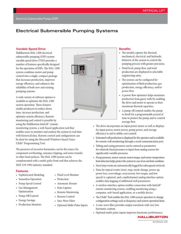
Halliburton’s HAL 1200 electrical
submersible pumping (ESP) system
variable speed drive (VSD) provides a
number of features specifically designed
for the operation of ESPs. The HAL 1200
system combines motor and pump
control into a single, compact package
that increases production, improves
energy efficiency, and enhances the
reliability of both new and existing
pumping systems.
A wide variety of software options is
available to optimize the HAL 1200
system operation. These features
enable producers to reduce down
time, increase production, and
optimize system efficiency. Remote
monitoring and control is possible by
using the Halliburton InteLift™ remote
monitoring system, a web-based application tool that
enables users to monitor and analyze the system in real time
with historical data. Remote control and configuration can
be done by using the Microsoft Windows-based Unico
UEdit® Programming Tool.
The presence of excessive harmonics can be the source for
component overheating, nuisance tripping, and noise transfer
to other load surfaces. The HAL 1200 system can be
complemented with a multi-pulse front end that achieves the
IEEE 519-1992 industry standard.
Features
• Sophisticated Modeling
• Sensorless Operation
• Pump Speed Control
• Gas Management
Optimization
• Pump-Off Control
• Energy Savings
• Production Monitors
•
•
•
•
•
•
•
•
Fluid Level Monitor
Protection
Automatic Restart
Data Capture
Remote Monitoring
Remote Control
Sine-Wave Filter
Optional Multi-Pulse Inputs
•
•
•
•
•
•
•
Benefits
• The models capture the thermal,
mechanical, electrical, and hydraulic
behavior of the system to control the
pumping process with greater precision.
• Fluid level, pump flow, and total
production are displayed in selectable
engineering units.
• The system can be configured for
optimization of fluid production, gas
production, energy efficiency, and/or
power flow.
• A power flow optimizer helps maximize
production from gassy wells by enabling
the drive and motor to operate at their
maximum thermal capacities.
• A pump-off control enables the pump
to dwell for a programmable period of
time to protect the pump and to control
average flow.
The drive incorporates an input power meter as well as displays
for input power, motor power, pump power, and average
efficiency to aid in utility cost control.
Estimated well production is displayed for the operator and is available
for remote well monitoring through a serial communication port.
Tubing and casing pressures can be entered as parameters
for relatively fixed pressures or input from analog sensors for
significantly variable pressures.
Pump pressure, motor current, motor torque, and motor-temperature
limit detection helps protect the system in case of an out limit condition.
Start/stop events are automatically logged for subsequent retrieval.
Data for typical events (start, stop, mode change, power up,
power loss, overvoltage, overcurrent, low torque, and low
speed) is captured, and a multichannel analog interface option
enables data logging of additional well parameters.
A wireless interface option enables connection with InteLift™
remote monitoring system, enabling monitoring using a
computer, web-based application, or a mobile device.
• The UEdit® Tool enables the HAL 1200 system operators to change
configuration settings such as frequency and system operation limit.
• A sine-wave filter provides output waveform with very low
harmonic content.
• Optional multi-pulse inputs improves harmonic performance.
Artificial Lift
ARTIFICIAL LIFT
Options
• Transducers—A motor-mounted incremental encoder or
resolver and corresponding interface may be used for highest
performance. The resolver interface provides an encoder
emulation for paralleling feedback to other devices. Dual- and
triple-encoder options are also available for position-following or
dual-transducer applications.
• Expanded Analog I/O—An analog interface module may be
used instead of a feedback interface to expand the analog I/O
capabilities of the drive. The module provides eight additional
inputs and four additional outputs.
• Dynamic Braking—Dynamic braking is included on small
units and is optionally available on higher-power units.
Appropriately sized external braking resistors are required.
• Packaged Drives—Drives may be ordered as part of a
packaged system including a circuit breaker, operator devices,
and additional system components mounted inside a NEMA 4
(IP66) enclosure.
Specifications
Parameter
Specification
Input Rating
Rated Input/Supply Voltage @ 50 Hz
230, 460, or 1150 V AC nominal (200 to 240, 380 to 480, or 950 to 1200 V AC),
three-phase (6-pulse); six-phase (12-pulse) available 50 hp CT and above;
twelve-phase (24-pulse) available on tandem drives Phase sequence insensitive
Voltage Tolerance
-50% of nominal, +15% of nominal (11/2 to 100 hp CT)
-15% of nominal, +15% of nominal (above 100 hp CT)
Rated Frequency (Hz)
47 to 63
Power Factor
Displacement: 1.00 at all loads and speeds Overall: 0.94 at rated load
Output Rating
Range of Output Voltage (V)
Zero to input supply voltage, three-phase
Frequency
Zero to 120 Hz for transducer less vector control Zero to 180 Hz for
transducer based vector control Zero to 300 Hz for variable-frequency control
Switching Frequency
1 to 12 kHz, programmable
Inverter Output
PWM
Service Conditions
Efficiency at Operation Conditions
97% nominal at rated switching frequency
Pulse Number of Rectifier
6
Overload Current
Torque Overload (1 min) Maximum
Constant 150 to 200% of rated 200% of rated
Variable 120 to 150% of rated 140% to 160% of rated
Extended 110 to 120% of rated 120% to 140% of rated
Environmental Specifications
Operating Temperature
Control section: -4 to 131°F (-20° to 55° C)
Heat sink (standard): -40 to 104°F (-40 to 40°C)
Heat sink (de-rated): -40 to 131°F (-40 to 55°C)
Storage Temperature
-40 to 158°F (-40 to 70°C)
Operating Humidity
95% maximum, noncondensing
Altitude
To 3,300 ft (1,000 m) without derating
Protection Rating
NEMA 3R
Overall Dimensions: in. (mm)
36 × 18 × 16 / 48 × 24 × 20 / 60 × 36 × 36 / 72 × 44 × 36
(914 × 457 × 406 / 1219 × 609 × 508 / 1524 × 914 × 914 / 1828 × 1117 × 914)
Communication
Communication to SCADA
ESP 1200 Communicates with InteLift™ Remote Monitoring System
Ports
One RS-232/422/485, isolated, and two auxiliary RS-422/485
Protocols
ANSI-x3.28-2.5-A4 or Modicon RTU, standard
ARTIFICIAL LIFT
Weatherproof Enclosure, NEMA 4
Model
Output HP
(amps)
Input volts
(amps)
Height
in. (mm)
Width
in. (mm)
Depth
in. (mm)
Weight
lb (kg)
1200-460-50RP
50 (65)
480 (56)
48 (121.9)
24 (61)
20 (50.8)
370 (168)
1200-460-60RP
60 (77)
480 (67)
48 (121.9)
24 (61)
20 (50.8)
370 (168)
1200-460-60
60 (77)
480 (66.8)
48 (121.9)
24 (61)
20 (50.8)
370 (168)
1200-460-75
75 (96)
480 (83.4)
48 (121.9)
24 (61)
20 (50.8)
370 (168)
1200-460-100
100 (124)
480 (109)
48 (121.9)
24 (61)
20 (50.8)
370 (168)
1200-460-125
125 (156)
480 (137)
48 (121.9)
24 (61)
20 (50.8)
500 (227)
1200-460-150
150 (180)
480 (161)
60 (152.4)
24 (61)
20 (50.8)
500 (227)
1200-460-200
200 (240)
480 (215)
60 (152.4)
36 (91.4)
36 (91.4)
800 (363)
1200-460-250
250 (300)
480 (269)
60 (152.4)
36 (91.4)
36 (91.4)
800 (363)
1200-460-300
300 (360)
480 (323)
60 (152.4)
36 (91.4)
36 (91.4)
1,000 (455)
1200-460-400
400 (480)
480 (430)
60 (152.4)
36 (91.4)
36 (91.4)
1,100 (500)
1200-460-500
500 (600)
480 (538)
72 (182.9)
54 (137.2)
36 (91.4)
1,500 (685)
1200-460-600
600 (720)
480 (646)
72 (182.9)
54 (137.2)
36 (91.4)
2,100 (955)
1200-460-800
800 (960)
480 (890)
72 (182.9)
54 (137.2)
36 (91.4)
2,100 (955)
1200-460-1000
1,000 (1,200)
480 (1,114)
72 (182.9)
54 (137.2)
36 (91.4)
2,100 (955)
Filters
Filter Description
Filter, Sine Wave 50 HP 460V
Filter, Sine Wave 60 HP 460V
Filter, Sine Wave 75 HP 460V
Filter, Sine Wave 100 HP 460V
Filter, Sine Wave 125 HP 460V
Filter, Sine Wave 150 HP 460V
Filter, Sine Wave 200 HP 460V
Filter, Sine Wave 250 HP 460V
Filter, Sine Wave 300 HP 460V
Filter, Sine Wave 400 HP 460V
Filter, Sine Wave 500 HP 460V
Filter, Sine Wave 600 HP 460V
Filter, Sine Wave 800 HP 460V
Filter, Sine Wave 1000 HP 460V
ARTIFICIAL LIFT
Delivery
All of the ESP pumps are fully integrated into Halliburton’s industry-leading,
customer-oriented global service network. Beginning at the manufacturing
plant in China, which has provided high-quality ESP systems for operators
across the globe for over a decade, and then to the Halliburton Field
Service Technician who supervises the installation and startup of the
pumps on site, Halliburton’s quality-management system helps solve
challenges at any stage of the process for operators in mature
fields, unconventional resources, and deepwater. Control
of this work flow enables continuous improvement in
the hydraulic designs so that they fit customer-specific
requirements, improve operating efficiencies, and adapt
to the dynamic conditions of the oil field.
Halliburton’s Artificial Lift offerings help operators
increase recoverable hydrocarbons by selecting the
optimal lift method over the life of the well cycle
to enhance well drawdown and provide reliable
on-stream times that can maximize revenue and
decrease costly well interventions, leading directly to
increased customer profitability. Another important
value to the customer is the ability of our Artificial Lift
representative to collaborate across other Halliburton
product lines so that the recommended solution is
optimal not only from the pump selection point of view
but also as it relates to delivering value to the reservoir.
Halliburton’s foundry provides high-quality
ESP stages and assembled/tested pumps for
a variety of customers and applications all
across the world.
Halliburton’s process entails the latest
technology in hydraulics, metallurgy,
machining, and assembly, and the
quality is assured through the rigorous
quality-management system.
Halliburton technicians accompany the
ESP systems to the field and supervise the
installation and startup to maximize success.
ARTIFICIAL LIFT
FAST
FACTS
Founded
Employees
1919
Nearly
75,000
Operational
Countries
Research
Centers
Corporate
Headquarters
80
15
Houston
Dubai
Customers
National, International,
and Independent
entities worldwide
Halliburton Locations
Halliburton Headquarters
Halliburton Research Centers
© 2013 HALLIBURTON. ALL RIGHTS RESERVED.
1
For more information, contact your local Halliburton representative
or visit us on the web at www.halliburton.com
© 2014 Halliburton. All rights reserved. Sales of Halliburton products and services will be in accord solely with the terms and conditions contained in the
contract between Halliburton and the customer that is applicable to the sale.
H011130 6/14
www.halliburton.com
Artificial Lift


