Pick and Place Output Options
Summary
The Pick and Place Setup Dialog
Pick and Place output
options are configured
in the Pick and Place
Setup dialog.
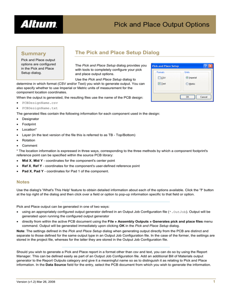
The Pick and Place Setup dialog provides you
with tools to completely configure your pick
and place output options.
Use the Pick and Place Setup dialog to
determine in which format (CSV and/or Text) you wish to generate output. You can
also specify whether to use Imperial or Metric units of measurement for the
component location coordinates.
When the output is generated, the resulting files use the name of the PCB design:
•
PCBDesignName.csv
•
PCBDesignName.txt
The generated files contain the following information for each component used in the design:
•
Designator
•
Footprint
•
Location*
•
Layer (in the text version of the file this is referred to as TB - Top/Bottom)
•
Rotation
•
Comment
* The location information is expressed in three ways, corresponding to the three methods by which a component footprint's
reference point can be specified within the source PCB library:
•
Mid X, Mid Y - coordinates for the component's center point
•
Ref X, Ref Y - coordinates for the component's user-defined reference point
•
Pad X, Pad Y - coordinates for Pad 1 of the component.
Notes
Use the dialog's 'What's This Help' feature to obtain detailed information about each of the options available. Click the '?' button
at the top right of the dialog and then click over a field or option to pop-up information specific to that field or option.
Pick and Place output can be generated in one of two ways:
•
using an appropriately configured output generator defined in an Output Job Configuration file (*.OutJob). Output will be
generated upon running the configured output generator
•
directly from within the active PCB document using the File » Assembly Outputs » Generates pick and place files menu
command. Output will be generated immediately upon clicking OK in the Pick and Place Setup dialog.
Note: The settings defined in the Pick and Place Setup dialog when generating output directly from the PCB are distinct and
separate to those defined for the same output type in an Output Job Configuration file. In the case of the former, the settings are
stored in the project file, whereas for the latter they are stored in the Output Job Configuration file.
Should you wish to generate a Pick and Place report in a format other than csv and text, you can do so by using the Report
Manager. This can be defined easily as part of an Output Job Configuration file. Add an additional Bill of Materials output
generator to the Report Outputs category and give it a meaningful name so as to distinguish it as relating to Pick and Place
information. In the Data Source field for the entry, select the PCB document from which you wish to generate the information.
Version (v1.2) Mar 26, 2008
1
OG0104 Pick and Place Output Options
Double-click on the entry. The dialog that appears will be named in accordance with the entry you specified for the output
generator's Name field - so if you named the generator Pick and Place, the dialog would appear with the header Pick and
Place for PCB Document [PCBName]. Then enable and configure the information columns for the report as required.
The output path for generated files is set in the Options tab of the Options for Project dialog. By default, the output path is set to
a sub-folder under the folder that contains the Project file and has the name: Project Outputs for ProjectName. The output
path can be changed as required. If the option to use a separate folder for each output type has been enabled in the Options
tab, then the Pick and Place files will be written to a further sub-folder, named: Pick Place Output.
When generated, the output will be added to the project and appear in the Projects panel under the Generated folder, in an
appropriately-named sub-folder. If you have used a separate folder for each output type, then corresponding (separate)
Generated folders will be added to the Projects panel (e.g. Generated (Pick Place Output)).
Version (v1.2) Mar 26, 2008
2
OG0104 Pick and Place Output Options
Revision History
Date
Version No.
Revision
05-Dec-2005
1.0
New release
04-Mar-2008
1.1
Updated Page size to A4.
26-Mar-2008
1.2
Minor edits and updates.
27-Jul-2011
-
Updated template.
Software, hardware, documentation and related materials:
Copyright © 2011 Altium Limited.
All rights reserved. You are permitted to print this document provided that (1) the use of such is for personal use only and will not be copied or
posted on any network computer or broadcast in any media, and (2) no modifications of the document is made. Unauthorized duplication, in
whole or part, of this document by any means, mechanical or electronic, including translation into another language, except for brief excerpts in
published reviews, is prohibited without the express written permission of Altium Limited. Unauthorized duplication of this work may also be
prohibited by local statute. Violators may be subject to both criminal and civil penalties, including fines and/or imprisonment.
Altium, Altium Designer, Board Insight, DXP, Innovation Station, LiveDesign, NanoBoard, NanoTalk, OpenBus, P-CAD, SimCode, Situs,
TASKING, and Topological Autorouting and their respective logos are trademarks or registered trademarks of Altium Limited or its subsidiaries.
All other registered or unregistered trademarks referenced herein are the property of their respective owners and no trademark rights to the
same are claimed.
Version (v1.2) Mar 26, 2008
3

