Conduit Rigid Entry Boots - Franklin Fueling Systems
advertisement
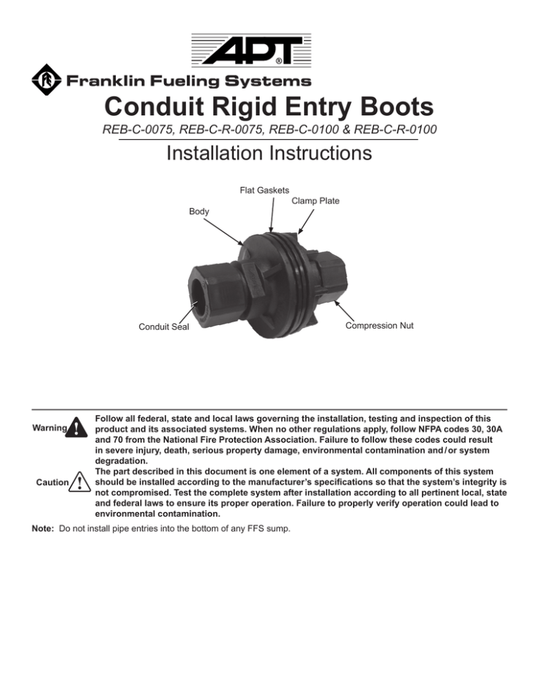
Conduit Rigid Entry Boots REB-C-0075, REB-C-R-0075, REB-C-0100 & REB-C-R-0100 Installation Instructions Flat Gaskets Body Conduit Seal Warning Caution Clamp Plate Compression Nut Follow all federal, state and local laws governing the installation, testing and inspection of this product and its associated systems. When no other regulations apply, follow NFPA codes 30, 30A and 70 from the National Fire Protection Association. Failure to follow these codes could result in severe injury, death, serious property damage, environmental contamination and / or system degradation. The part described in this document is one element of a system. All components of this system should be installed according to the manufacturer’s specifications so that the system’s integrity is not compromised. Test the complete system after installation according to all pertinent local, state and federal laws to ensure its proper operation. Failure to properly verify operation could lead to environmental contamination. Note: Do not install pipe entries into the bottom of any FFS sump. 1. Installation in Poly Sumps Note: See page 3 for round sump installation 1. Mark hole location for the piping entrance. Note: Tapered gasket and Adapter Ring are used only with round sumps, and supplied with REBC-R-0075 and REB-C-R-0100 fittings only. 5. Install the second gasket on the inside. Note: Mark the hole so the bottom edge of the fitting is at least 2" from the bottom of the sump. Sump Interior Figure 4: Install Inside Gasket Figure 1: Mark Location 6. Screw on the Clamp Plate on the fitting from the inside of the sump. 2. Drill a 2 ¾” hole where the sump is marked. Figure 2: Drill 2 ¾" Hole 3. Remove Clamp Plate. Sump Exterior Figure 5: Install Clamp Plate 7. Tighten the Clamp Plate hand-tight Use a spanner wrench to turn the Clamp Plate an additional ¼ turn. Gasket Figure 6: Tighten Clamp Plate Note: Do NOT over-tighten the fitting. Figure 3: Insert Fitting 4. Place fitting and flat gasket in opening from the outside. 2 Use a spanner wrench or chain wrench. Do NOT use pipewrenches or adjustable / slip joint pliers. 8. Insert the conduit piping into the fitting. 2. Installing the Fitting in a Round Fiberglass Sump The REB-C-R-0075 and REB-C-R-0100 fitting can be installed on round sumps with a diameter of 42” (1066.8 cm) or greater. The process is the same as shown earlier with one important difference: this assembly requires (1) double-tapered gasket and (1) adapter ring instead of the one seal used for flat surfaces. Note: Mark the hole so the bottom edge of the fitting is at least 2" from the bottom of the sump. 1. After the hole is drilled in the fiberglass sump, use 80 grit sandpaper to roughen the inside surface for 2" around the opening. Figure 7: Insert Conduit and Tighten Compression Nut Sump Interior 9. Tighten the Compression Nut on the inside of the sump using a parallel jaw wrench. Exterior Figure 9: Sand AroundSump Hole Interior Figure 8: Tighten Outside Compression Nut Because of the uneven surface of a FRP sump, a higher torque may be needed to seal the entry boot properly. We recommend an additional ¼ turn on the nut. If a leak occurs during the hydrostatic test, add an additional torque of ¼ turn at a time on the fitting. Figure 10: Sand Around Hole Exterior 2. Clean the sanded area with acetone. 3 3. From the outside, install the double-tapered gasket between the fitting and the sump. Position the gasket such that the tab and the wide thickness is to the sides. 5. Make sure the tab on the Adapter Ring is on top (Figure 13). Sump Interior Note Tab Position Figure 13: Adapter Ring installed on Inside of Sump Figure 11: Gasket Orientation Outside of Sump 5. Hand-tighten the locking ring. Mark the fitting / sump with 2 marks 90º apart. 4. From the inside of the sump, install the Adapter Ring on the fitting. Position this ring such that the sump note faces the sump wall. Figure 14: 90º Marks on Sump Interior Figure 12: Adapter Ring 4 6. Use a spanner wrench or chain wrench to tighten the locking ring 90º from the hand-tightened position. Figure 15: Tighten Locking Ring Because of the uneven surface of a FRP sump, a higher torque may be needed to seal the entry boot properly. If a leak occurs during the hydrostatic test, add an additional torque of no more than ¼ turn at a time on the fitting. 7. Insert the conduit piping into the fitting. Figure 16: Insert Conduit and Tighten Compression Nut 8. Tighten the Compression Nut on the inside of the sump using a parallel jaw wrench. 5 ©2014 FFS 771-125-00 Rev. 3
