WattStationTM Wall Mount: Installation Guide Plug
advertisement
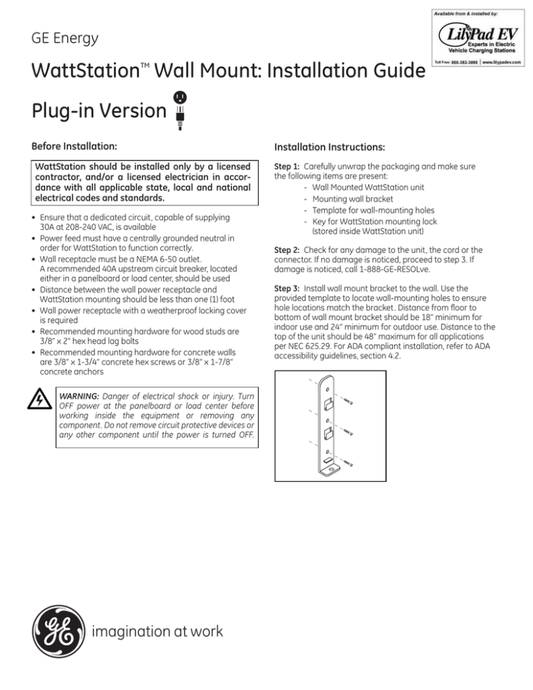
GE Energy WattStation Wall Mount: Installation Guide TM Plug-in Version Before Installation: WattStation should be installed only by a licensed contractor, and/or a licensed electrician in accordance with all applicable state, local and national electrical codes and standards. • • • • • Ensure that a dedicated circuit, capable of supplying 30A at 208-240 VAC, is available Power feed must have a centrally grounded neutral in order for WattStation to function correctly. Wall receptacle must be a NEMA 6-50 outlet. A recommended 40A upstream circuit breaker, located either in a panelboard or load center, should be used Distance between the wall power receptacle and WattStation mounting should be less than one (1) foot Wall power receptacle with a weatherproof locking cover is required • Recommended mounting hardware for wood studs are 3/8” x 2” hex head lag bolts • Recommended mounting hardware for concrete walls are 3/8” x 1-3/4” concrete hex screws or 3/8” x 1-7/8” concrete anchors Installation Instructions: Step 1: Carefully unwrap the packaging and make sure the following items are present: - Wall Mounted WattStation unit - Mounting wall bracket - Template for wall-mounting holes - Key for WattStation mounting lock (stored inside WattStation unit) Step 2: Check for any damage to the unit, the cord or the connector. If no damage is noticed, proceed to step 3. If damage is noticed, call 1-888-GE-RESOLve. Step 3: Install wall mount bracket to the wall. Use the provided template to locate wall-mounting holes to ensure hole locations match the bracket. Distance from floor to bottom of wall mount bracket should be 18” minimum for indoor use and 24” minimum for outdoor use. Distance to the top of the unit should be 48” maximum for all applications per NEC 625.29. For ADA compliant installation, refer to ADA accessibility guidelines, section 4.2. WARNING: Danger of electrical shock or injury. Turn OFF power at the panelboard or load center before working inside the equipment or removing any component. Do not remove circuit protective devices or any other component until the power is turned OFF. STEP (3 PI & HW) imagination at work Step 6: Unwrap the plug-in cord and plug into the wall receptacle Step 4: Slide WattStation unit onto the mounting bracket, ensuring that the opening in the back plate bracket aligns with the tab on the wall mount bracket STEP 6 (PI) Step 7: Lock weatherproof receptacle cover (not supplied with WattStation) STEP 4 (PI) Step 5: Lock the WattStation unit onto the mounting bracket using the provided key STEP 7 (PI) STEP 5 (PI) GE Energy 41 Woodford Avenue Plainville, CT 06062 www.geindustrial.com © 2011 GE Company imagination at work WattStationTM is a trademark of General Electric Company. DET-751 (07/11)
