The ideal regenerative Rankine cycle
advertisement
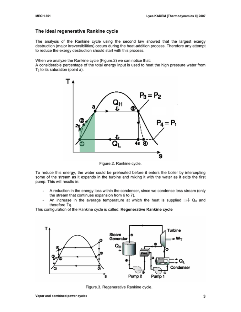
MECH 351 Lyes KADEM [Thermodynamics II] 2007 The ideal regenerative Rankine cycle The analysis of the Rankine cycle using the second law showed that the largest exergy destruction (major irreversibilities) occurs during the heat-addition process. Therefore any attempt to reduce the exergy destruction should start with this process. When we analyze the Rankine cycle (Figure.2) we can notice that: A considerable percentage of the total energy input is used to heat the high pressure water from T2 to its saturation (point a). Figure.2. Rankine cycle. To reduce this energy, the water could be preheated before it enters the boiler by intercepting some of the stream as it expands in the turbine and mixing it with the water as it exits the first pump. This will results in: A reduction in the energy loss within the condenser, since we condense less stream (only the stream that continues expansion from 6 to 7). - An increase in the average temperature at which the heat is supplied ⇒↓ QH and therefore ↑η. This configuration of the Rankine cycle is called: Regenerative Rankine cycle - Figure.3. Regenerative Rankine cycle. Vapor and combined power cycles 3 MECH 351 Lyes KADEM [Thermodynamics II] 2007 The heat transfer between the intercepted stream and the high-pressure water (called feedwater) occurs in what we call: feedwater heaters (FWH). A feedwater is basically a heat exchanger where heat is transferred from the high temperature stream to low temperature feedwater. This can be performed by: - A direct mixing (open feedwater heater). - Without mixing (closed feedwater heater). Rmq: sometimes, the feedwater heater is called a regenerator. The mass flow between (6-7) is different from the mass flow from (6-3) NOTE: The mass flow rate varies in the regenerative Rankine cycle. - Open feedwater heater (direct contact) Turbine stream Saturated liquid out Cold water in Figure 4. Open feedwater heater. Advantages - Simple - Inexpensive - Have good heat transfer characteristics - Bring feedwater into saturated state Disadvantages - For each heater, we need a pump Problem: the cold water and the turbine stream must be at the same pressure. - Closed feedwater heater ( no mixing) The two streams now can be at different pressures since they do not mix. The water passes through in the tubes and steam surrounds the tubes. The steam is condensated and pumped by a condensate pump into the main feedwater line or it passes through a trap (a device that permits only liquids to pass through). Advantages - We don’t need a pump for each heater, since the pressure is different Disadvantages - More complex (internal tubing network) - More expensive - Less heat transfer performance, since the two fluids are not in contact. Vapor and combined power cycles 4 MECH 351 Lyes KADEM [Thermodynamics II] 2007 Figure 5. Closed feedwater heater. Figure 6. A feedwater heater. Figure 7. A steam trap system. Vapor and combined power cycles 5 MECH 351 Lyes KADEM [Thermodynamics II] 2007 Rmq: usually modern steam power plants use a combination of open and closed feedwater heaters. - Optimal number of feedwater heaters All modern steam power plants use feedwater heaters (8 feedwater heaters). The optimum number of feedwater heaters is determined from economical considerations: You add a feedwater heater only if it saves more fuel than its own cost (+ maintenance). With a large number of heaters, it is possible to approach the Carnot efficiency but at an unjustifiably high cost. - At which pressure, the steam must be extracted from the turbine? The pressure at which the steam should be extracted from the turbine must be in such a way that for one heater, the steam should be extracted at the point that allows the existing feedwater heater temperature to be midway between the saturated steam temperature in the boiler and the condenser temperature. For several heaters, the temperature difference should be divided as equally as possible. Rmq: The regeneration cycle increases the thermal efficiency, but it is affected by the moisture at the outlet of the turbine, therefore, it is not uncommon to combine a reheat cycle and a regeneration cycle. Example Consider a regenerative cycle using steamas the working fluid. Steam leaves the boiler and enters the turbine at 4 MPa and 400°C. After expansion to 400 kPa, some of the steam is extracted from the turbine for the purpose of heating the feedwater in an open feedwater heater. The pressure in the feedwater heater is 400 kPa and the water leaving it is saturated liquid at 400 kPa. The steam not extracted expands to 10 kPa. Determine the cycle efficiency Vapor and combined power cycles 6
