INF5481 RF Circuit, Theory and Design Assignment #2
advertisement
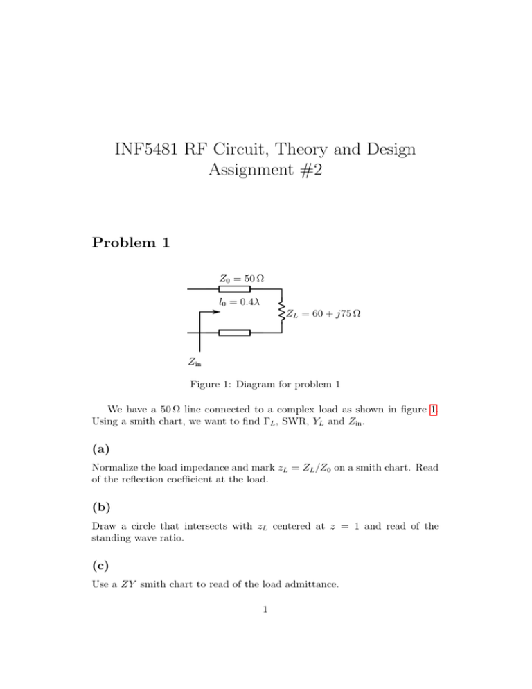
INF5481 RF Circuit, Theory and Design Assignment #2 Problem 1 Z0 = 50 Ω l0 = 0.4λ ZL = 60 + j75 Ω Zin Figure 1: Diagram for problem 1 We have a 50 Ω line connected to a complex load as shown in figure 1. Using a smith chart, we want to find ΓL , SWR, YL and Zin . (a) Normalize the load impedance and mark zL = ZL /Z0 on a smith chart. Read of the reflection coefficient at the load. (b) Draw a circle that intersects with zL centered at z = 1 and read of the standing wave ratio. (c) Use a ZY smith chart to read of the load admittance. 1 INF5481: Assignment #2 (d) Rotate the load reflection coefficient from l = 0 to l = 0.4λ, read of the input impedance. Problem 2 l7 = λ/4 C8 = 2.2 pF l5 = λ/4 l6 = 0.4λ l3 = 0.15λ R4 = 33 Ω L2 = 2 nH R1 = 85 Ω Z0 = 50 Ω Zin Figure 2: Diagram for problem 2, all transmission lines are lossless and 50 Ω. In a patent for a GSM900 receiver circuit working at 940 MHz, you find the circuit diagram in figure 2. You decide to investigate the circuit using a smith chart. Start at the load and work you way to the input, show intermediate steps and give the un-normalized input impedance Zin . If you arrived around 30 Ω, can you think of a simpler circuit to transform a 85 Ω load to 30 Ω? Problem 3 We now study the shorted and open transmission lines in figure 3. (a) Find the required length l0 to achive an input impedance Zin = −25j Ω. (b) Find the required length l1 to achive an input admitance Yin = 0.04j Ω. Is your answer unique? Page 2 of 3 INF5481: Assignment #2 Z0 = 50 Ω Z0 = 50 Ω l0 =? l1 =? ZL = ∞ ZL = 0 Zin = −25j Ω Yin = 0.04j Ω (a) Short circuit (b) Open Figure 3: Diagrams for problem 3 Problem 4 We have the complex load in figure 4, which we want to match to Zin = 50 Ω. Use a smith chart to find the required values for L and C at 100 MHz. L C Zload = 10 + 40j Ω Zin = 50 Ω Figure 4: Diagram for problem 4 Page 3 of 3
