Example 4-9: Input impedance computation of a transmission line
advertisement
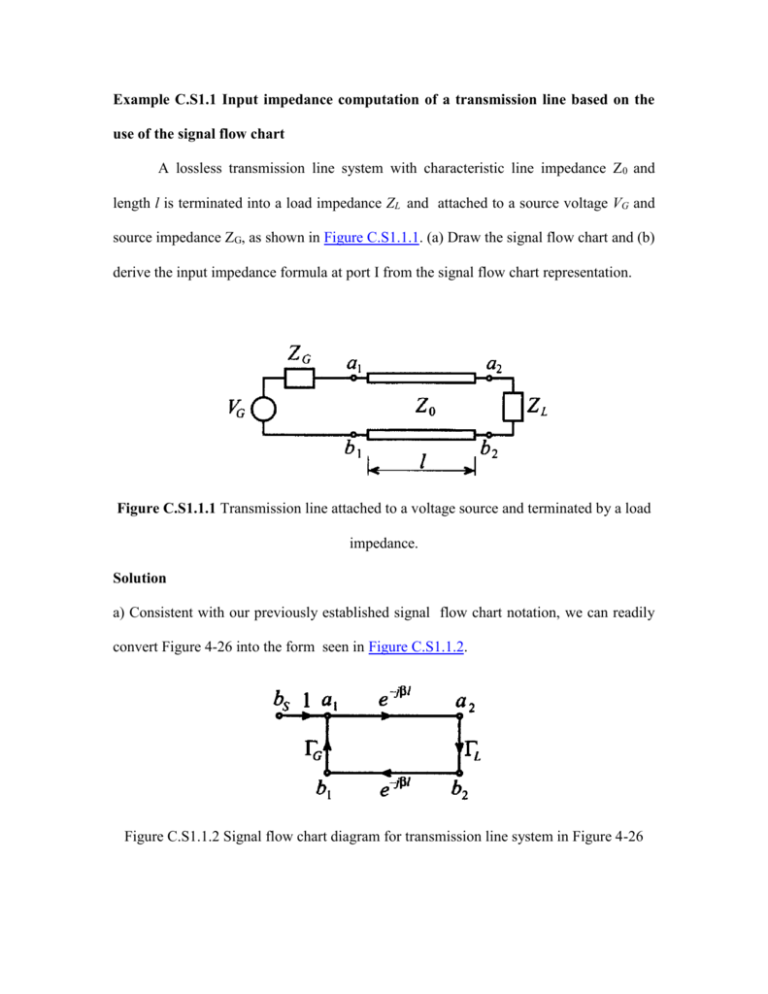
Example C.S1.1 Input impedance computation of a transmission line based on the use of the signal flow chart A lossless transmission line system with characteristic line impedance Z0 and length l is terminated into a load impedance ZL and attached to a source voltage VG and source impedance ZG, as shown in Figure C.S1.1.1. (a) Draw the signal flow chart and (b) derive the input impedance formula at port I from the signal flow chart representation. Figure C.S1.1.1 Transmission line attached to a voltage source and terminated by a load impedance. Solution a) Consistent with our previously established signal flow chart notation, we can readily convert Figure 4-26 into the form seen in Figure C.S1.1.2. Figure C.S1.1.2 Signal flow chart diagram for transmission line system in Figure 4-26 b) The input reflection coefficient at port 1 is given by b1 L e j2l a 1 thus, in (l) L e 2 jl Zin Z 0 Zin Z 0 Solving for Zin yields the final result Zin Z0 1 L e 2 jl 1 L e 2 jl This example shows how the input impedance of a transmission line can be found quickly and elegantly by using signal flowchart concept.
