Incremental Conductance Based Maximum Power Point
advertisement

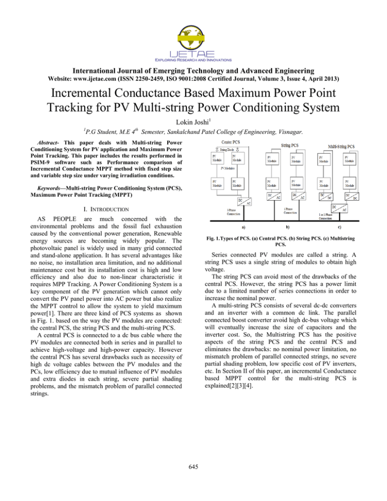
International Journal of Emerging Technology and Advanced Engineering Website: www.ijetae.com (ISSN 2250-2459, ISO 9001:2008 Certified Journal, Volume 3, Issue 4, April 2013) Incremental Conductance Based Maximum Power Point Tracking for PV Multi-string Power Conditioning System Lokin Joshi1 1 P.G Student, M.E 4 th Semester, Sankalchand Patel College of Engineering, Visnagar. Abstract- This paper deals with Multi-string Power Conditioning System for PV application and Maximum Power Point Tracking. This paper includes the results performed in PSIM-9 software such as Performance comparison of Incremental Conductance MPPT method with fixed step size and variable step size under varying irradiation conditions. Keywords—Multi-string Power Conditioning System (PCS), Maximum Power Point Tracking (MPPT) I. INTRODUCTION AS PEOPLE are much concerned with the environmental problems and the fossil fuel exhaustion caused by the conventional power generation, Renewable energy sources are becoming widely popular. The photovoltaic panel is widely used in many grid connected and stand-alone application. It has several advantages like no noise, no installation area limitation, and no additional maintenance cost but its installation cost is high and low efficiency and also due to non-linear characteristic it requires MPP Tracking. A Power Conditioning System is a key component of the PV generation which cannot only convert the PV panel power into AC power but also realize the MPPT control to allow the system to yield maximum power[1]. There are three kind of PCS systems as shown in Fig. 1. based on the way the PV modules are connected: the central PCS, the string PCS and the multi-string PCS. A central PCS is connected to a dc bus cable where the PV modules are connected both in series and in parallel to achieve high-voltage and high-power capacity. However the central PCS has several drawbacks such as necessity of high dc voltage cables between the PV modules and the PCs, low efficiency due to mutual influence of PV modules and extra diodes in each string, severe partial shading problems, and the mismatch problem of parallel connected strings. Fig. 1. Types of PCS. (a) Central PCS. (b) String PCS. (c) Multistring PCS. Series connected PV modules are called a string. A string PCS uses a single string of modules to obtain high voltage. The string PCS can avoid most of the drawbacks of the central PCS. However, the string PCS has a power limit due to a limited number of series connections in order to increase the nominal power. A multi-string PCS consists of several dc-dc converters and an inverter with a common dc link. The parallel connected boost converter avoid high dc-bus voltage which will eventually increase the size of capacitors and the inverter cost. So, the Multistring PCS has the positive aspects of the string PCS and the central PCS and eliminates the drawbacks: no nominal power limitation, no mismatch problem of parallel connected strings, no severe partial shading problem, low specific cost of PV inverters, etc. In Section II of this paper, an incremental Conductance based MPPT control for the multi-string PCS is explained[2][3][4]. 645 International Journal of Emerging Technology and Advanced Engineering Website: www.ijetae.com (ISSN 2250-2459, ISO 9001:2008 Certified Journal, Volume 3, Issue 4, April 2013) PV cells have a single operating point where the values of current and voltage result in a maximum power output for the cell. Maximum power point tracker is basically an electronic system that controls the duty circuit of the converter to enable the photovoltaic module operate at maximum operating power at all condition. The advantages of MPPT regulators are greatest during cloudy or hazy days or cold weather. There are different types of maximum power point tracking methods developed over the years and they are listed below as follows (1) Perturb and observe method, (2)Incremental conductance method, (3) Artificial neutral network method, II. MULTISTRING CONVERTER A. Circuit Configuration The multi-string PV PCS is utilized as shown in Fig. 2. This system is composed of two boost converters and a single-phase full-bridge inverter. Two identical boost converters are designed at 50% of the rated power. Each boost converter performs its own MPPT control. Fig. 2. Multistring PV single-phase PCS. Fig. 3. Basic idea of IncCond method on a P-V curve of solar array. (y axis div. 1 section=100 w) The full-bridge inverter regulates the dc link voltage and converts dc power into ac power. As the dc link voltage is increased, the inverter increases the output power. On the contrary, as the dc link voltage is decreased, the inverter decreases the output power. The bulky 50 Hz isolation transformer is excluded in the inverter. This transformer less full-bridge inverter has the advantages of small size and low cost. Fig.4. Flow chart of INC method with fixed step size. (4) Fuzzy logic method, (5) Peak power point method, (6) Open circuit voltage method, and (7) Temperature method etc.[5] The MPPT plays a very significant role because without the MPPT the desire output electrical power will not be achieve with changing weather conditions. B. MPPT Systems A maximum power point tracker is a high-efficiency DC-DC converter, which functions as an optimal electrical load for photovoltaic cell, most commonly used for a solar panel or array and converts the power to a voltage or current level which is more suitable to whatever load the system is design to drive. 646 International Journal of Emerging Technology and Advanced Engineering Website: www.ijetae.com (ISSN 2250-2459, ISO 9001:2008 Certified Journal, Volume 3, Issue 4, April 2013) [ ( C. INC Method with fixed step size. In incremental conductance method with fixed step size the array terminal voltage is always adjusted according to the MPP voltage it is based on the incremental and instantaneous conductance of the PV module. Fig. 3. shows that the slope of the P-V array power curve is zero at The MPP, increasing on the left of the MPP and decreasing on the Right hand side of the MPP. The basic equations of this method are as follows. At MPP At Left of MPP At Right of MPP )] (5) At MPP, (6) The above equation could be written in terms of array voltage V and array current I as, (7) The MPPT regulates the PWM control signal of the dc to dc boost converter until the condition (dI/dV) + (I/V) = 0 is satisfied. (1) (2) (3) Fig.5. Variation of Normalized Power and dP/dV versus voltage curve. Where I and V are P-V array output current and voltage respectively. The left hand side of equations represents incremental conductance of P-V module and the right hand side represents the instantaneous conductance. When the ratio of change in output conductance is equal to the negative output conductance, the solar array will operate at the maximum power point. This method exploits the assumption of the ratio of change in output conductance is equal to the negative output Conductance Instantaneous conductance[6]. (4) Fig.6. Flow chart of INC method with variable step size. D. INC Method with Variable step size. The Incremental Conductance MPTT algorithm usually uses a fixed iteration step size, which is determined by the accuracy and tracking speed requirement. Thus, the corresponding design should satisfactorily address the tradeoff between the dynamics and steady state oscillations. Applying the chain rule for the derivative of products yields to, 647 International Journal of Emerging Technology and Advanced Engineering Website: www.ijetae.com (ISSN 2250-2459, ISO 9001:2008 Certified Journal, Volume 3, Issue 4, April 2013) To solve these problems, a modified INC MPPT with variable step size is proposed in this paper. The step size is automatically tuned according to the inherent PV array characteristics. If the operating point is far from MPP, it increases the step size which enables a fast tracking ability. If the operating point is near to the MPP, the step size becomes very small that the oscillation is well reduced contributing to a higher efficiency and also it can effectively improve the dynamic performance and steady state performance simultaneously[7]. The PV output power and slope of output power versus output voltage curves are shown in figure. 5. Equation for the step size is, | | If this cannot be satisfied, the variable step size INC MPPT will be working with a fixed step size of the previously set upper limiter ΔDmax. This equation provides a simple guidance to determine the scaling factor N of the variable step size INC MPPT algorithm.With the satisfaction of this equation, larger N exhibits a comparatively faster response than a smaller N. III. SIMULATION ON PV MULTISTRING PCS. A simple MPPT PV system shown in Fig. 6 is simulated in PSIM-9 to test the feasibility of the proposed method. PV array specifications are shown in table I. A boost converter and full bridge inverter is used as the power interface between the PV array and the load to achieve maximum power. the output voltage of the boost converter can be expressed as, (8) (11) TABLE I PV Array Specification No. of Cells(NS) Short-Circuit Current(ISC) Open-Circuit Voltage(VOC) Maximum Power(PMAX) 4*48 8.32 A 117.6 V 500 W Fig.7. PV Multistring Power Conditioning System with MPPT control. To ensure the convergence of the MPPT update rule, the variable step rule must obey the following: | | (9) Where, | | operation of obtained as, (a) PV array Max Power and Output Power. (y axis div. 1 section=100 w) is the | | at fixed step size .The scaling factor can therefore be ⁄| | (10) 648 International Journal of Emerging Technology and Advanced Engineering Website: www.ijetae.com (ISSN 2250-2459, ISO 9001:2008 Certified Journal, Volume 3, Issue 4, April 2013) (b) Change in Duty cycle. (y axis div. 1 section=0.05 v) (b) Change in Duty cycle. (y axis div. 1 section=0.05 v) Fig.9. PV array Output Power and Change in duty cycle with variable size INC MPPT. (a) PV array max power and output power. (b) Change in Duty cycle. (N=0.1) Fig.8. PV array Output Power and Change in duty cycle with fixed size INC MPPT. (a) PV array max power and output power. (b) Change in Duty cycle. (ΔD=0.05) The duty cycle command is therefore updated every 0.05 ms. The output power performance of INC MPPT with fixed step size 0.05 under irradiation step change conditions are shown in Fig. 7. The irradiation was suddenly changed from 1000 to 800 W/m2 at 0.35 s and changed back to 1000 W/m2 at 0.71 s. For the comparative purpose, the allowable maximum duty size ΔDmax is set as 0.05 for the proposed variable step size INC MPPT method. The corresponding PV output power and step size under N = 0.1 are shown in Figs. 8 respectively. The tracking performance under both fixed and variable INC MPPT methods are presented. The PV array average output power with fixed step size of 0.05 is 453.22 W. The proposed variable step size method reduces the oscillations at stead state due to the very small dP/dV and the PV array output power is 457.36 W. Moreover, the dynamic performance is obviously faster than that of fixed step size of 0.05. Where D is the Duty cycle. It can be seen that the input dc voltage can be easily shifted to a high level. Boost converter have higher efficiency than other topologies, and also it can achieve maximum charging effect using minimum number of PV modules. The very low number of component is a security against failures and increases the mean time before failure. To compare the performance of the variable step size INC MPPT method with the ordinary fixed step size INC MPPT method, the simulation are configured under exactly the same Condition to compare the performances. The PV array in simulation is composed of four PV module, and the sampling period used for MPPT algorithm is chosen as 0.05 ms. IV. CONCLUSION (a) The photovoltaic Multistring power conditioning system with MPPT control using fixed step size and variable step size incremental conductance method have been analyzed by simulation. The fixed step-size incremental conductance algorithm can’t meet tracking speed and steady-state accuracy of the PV system simultaneously, the value of tracking step-size is determined by the system performance requirements. In this paper, the variable step-size incremental conductance algorithm has been presented, which is able to automatically adjusted according to dP/dV characteristics of PV system. If the working point is far from MPP, step-size is increased to achieve fast dynamic response. PV array Max Power and Output Power. (y axis div. 1 section=100 w) 649 International Journal of Emerging Technology and Advanced Engineering Website: www.ijetae.com (ISSN 2250-2459, ISO 9001:2008 Certified Journal, Volume 3, Issue 4, April 2013) [4] Whereas the working point is near to the MPP, step-size is small to reducing the oscillation and improving the efficiency of the PV system. [5] REFERENCE [1] [2] [3] Mike Meinhardt, Gunther Cramer,Bruno Burger,Peter Zacharias,” ulti-String- Converter with Reduced Specific Costs and Enhanced Functionality”. W.-Toke Franke, Nils Oestreich, Friedrich W. Fuchs,“Comparison of Transformerless Converter Topologies for Photovoltaic Application Concerning Efficiency and Mechanical Volume“,IEEEJULY 2010, p-724-729. Jung-Min Kwon, Bong-Hwan Kwon, and Kwang-Hee Nam,” GridConnected Photovoltaic Multistring PCS With PV Current Variation Reduction Control” , IEEE Transaction on Industrial Electronics, NOV 2009, vol. 56, No.11. [6] [7] 650 M.I.Desconzi, R.C.Beltrame, C.Rech, L.Schuch, and H.L.Hey“Photovoltaic Stand-Alone Power Generation System with Multilevel Inverter” International Conference on Renewable Energies and Power Quality,APRIL 2010. Roberto Faranda, Sonia Leva,” Energy Comparison of MPPT techniques for PV system”,WSEAS transactions of power systems, JUNE 2008, issue-6, vol 3. M.Lokanadham, K.Vijaya Bhaskar,” Incremental Conductance based Maximum Power Point Tracking for Photovoltaic system”, IJERA-march-APRIL 2012, issue-2, p-1420-1424. Fangrui Liu, Shanxu Duan, Fei Liu, Bangyin Liu and Yong Kang,“A variable step size INC MPPT method for PV system”, IEEE transaction on industrial electronics, vol. 55, no. 7, JULY 2008


