PIV

Rectifier Circuits
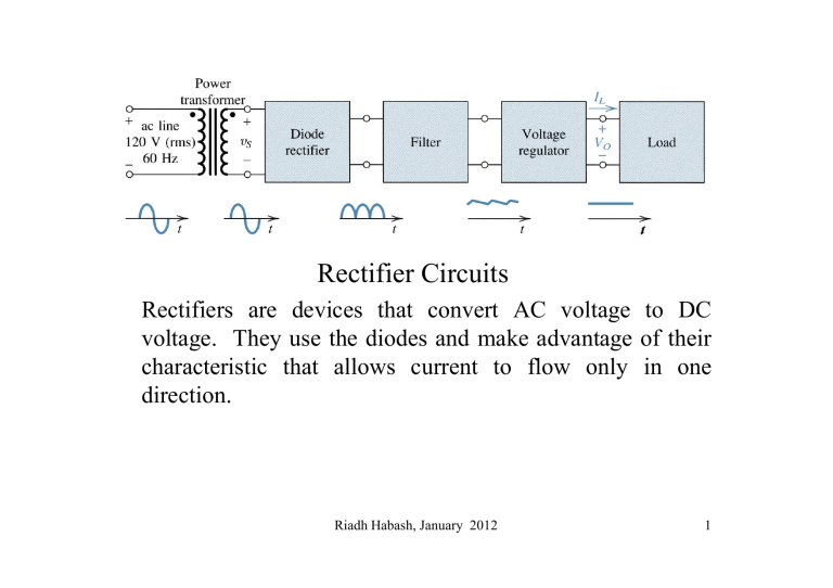
Rectifiers are devices that convert AC voltage to DC voltage. They use the diodes and make advantage of their characteristic that allows current to flow only in one direction.
Riadh Habash, January 2012 1
120V (rms)
60 Hz
Basic Components
Ripples minimized
15 V dc
Transformer
Input Stepped down to a lower voltage, e.g.,
15 V
Polarity is changing
Rectifier
Zener diode Regulator
Undesired ripples
Filter
Single polarity
v o
= v s
−
V
D
Half-Wave Rectifier
PIV
=
V s
Riadh Habash, January 2012 3
Breakdown
How or when can it occur?
Diodes are usually marked by their PIV rating. A diode with low PIV rating (i.e., one that breaks down at small negative voltage) is cheaper and easier to manufacture, while another one that has a high PIV rating can sustain a large negative voltage without breakdown
What is PIV?
The PIV for this half-wave single diode rectifier is the peak value
In other words, to design a half-wave rectifier using a single diode, we need to use a diode whose
PIV is higher than
V
S
, which is the peak value of the source voltage
For example, if V
S is 10 V, then it would be safer to choose a diode whose V
ZK higher than, e.g. is 40 % bigger than V
S
Full-Wave Rectifier
PIV
=
2 V s
−
V
D 0
Riadh Habash, January 2012 6
Comparison Between
Half- and Full Wave Rectifier in terms of the PIV
PIV
( One-diode Half-Wave)
= V
S
PIV
( Two-diode Full-Wave)
= 2V
S
-V
DO
That is bad, because it means that we will need to use a diode with a higher PIV rating
Bridge Rectifier
The bridge rectifier acts as a fullwave rectifier. In additions it does suffer from the high PIV requirement needed in the two-diode full-wave rectifier presented earlier.
The Bridge Rectifier
PIV
=
V s
−
V
D 0
Riadh Habash, January 2012 9
PIV for the Bridge Rectifier
Since
Also
KVL
Hence
Consider this diode in the reverse-region
To avoid breakdown, we need to know the maximum negative voltage that v
D3 experience can
PIV for the Bridge Rectifier
Becomes the lowest negative, when reaches its maximum or peak value of
Hence,
Comparison Between Rectifiers in terms of their
PIV voltages
PIV
( One-diode Half-Wave)
= V
S
PIV
( Two-diode Full-Wave)
= 2V
S
-V
DO
PIV
( Bridge rectifier)
= V
S
-V
DO
Worst
Better
i
L i
D
= v
R
0
= i
C
+ i
L i
D
=
C d vI dt
+ i
L
The Half-Wave Peak Rectifier
I
L
=
V p
R
V o v o
=
V p
−
1
2
V r
=
V p e
− t / CR
V p
−
V r
=
V p e
−
T / RC
V r
≈
V p
T
V p
RC
V r
= fCR
Riadh Habash, January 2012 i
Dav i
D max
=
=
I
L
I
L
1
(
1
(
+
+
π
2
π
2 V p
/ V r
2 V p
13 /
)
V r
)
We need to make v
O
Slowly Decaying,
How Can we achieve that?
We can choose
This will make the discharge time longer and the output voltage will not decay quickly
When
The picture in steady-state
We need to calculate those values
The picture at Steady-State
As if the output is following the peak of the shadow of negative cycle in the input waveform
Full-Wave Peak Rectifier Ideal Diodes
Half-wave Peak Rectifier
Gets halved
Same
Same
Same
Full-wave Peak Rectifier


