PDF 357KB
advertisement

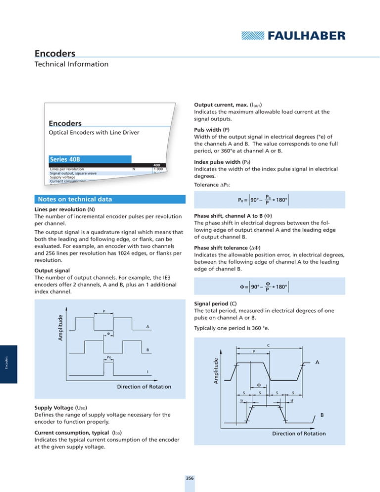
Encoders Technical Information Output current, max. (l OUT) Indicates the maximum allowable load current at the signal outputs. Encoders Puls width (P) Width of the output signal in electrical degrees (°e) of the channels A and B. The value corresponds to one full period, or 360°e at channel A or B. Optical Encoders with Line Driver Series 40B Lines per revolution Signal output, square wave Supply voltage Current consumption, max. (VCC = 5 V DC) Pulse width Index pulse width (P0) Indicates the width of the index pulse signal in electrical degrees. 40B 1 000 2 + 1 index an 4,5 ... 5,5 100 180 ± 18 N V CC I CC P Tolerance ΔP0: Notes on technical data P0 = 90° – Lines per revolution (N) The number of incremental encoder pulses per revolution per channel. Phase shift, channel A to B (⌽) The phase shift in electrical degrees between the following edge of output channel A and the leading edge of output channel B. The output signal is a quadrature signal which means that both the leading and following edge, or flank, can be evaluated. For example, an encoder with two channels and 256 lines per revolution has 1024 edges, or flanks per revolution. Phase shift tolerance (Δ⌽) Indicates the allowable position error, in electrical degrees, between the following edge of channel A to the leading edge of channel B. Output signal The number of output channels. For example, the IE3 encoders offer 2 channels, A and B, plus an 1 additional index channel. Φ = 90° – Φ 180° P * Signal period (C) The total period, measured in electrical degrees of one pulse on channel A or B. P Amplitude P0 180° P * A Typically one period is 360 °e. Φ C B P Amplitude Encoders Po I A Φ Direction of Rotation S tr Supply Voltage (UDD) Defines the range of supply voltage necessary for the encoder to function properly. S S tf B Current consumption, typical (IDD) Indicates the typical current consumption of the encoder at the given supply voltage. 40B front.indd 1 S Direction of Rotation 356 14.03.12 10:52 Synchronous serial interface The synchronous serial interface (SSI) is an interface for absolute encoders with which absolute position information is supplied via serial data transfer. Position value transfer is synchronized with a clock rate defined by a control. Logic state width (S) The distance measured in electrical degrees (°e) between two neighbouring signal edges, for example the leading edge of signal A to the leading edge of signal B. Typically this has a value of 90 °e. Signal rise/fall time, typical (tr/tf) Corresponds to the slope of the rising and falling signal edges. Steps per revolution Steps per revolution indicates the number of position values per motor revolution. Frequency range (f) Indicates the maximum encoder frequency. The maximum achievable motor speed can be derived using the following formula. n= Set-up time after power on Maximum time to availability of the output signals, as of when supply voltage is applied. Clock frequency max. Maximal permissible clock frequency for reading the extended synchronous serial interface. 60 . f N Inertia of the code disc (J) Indicates the additional inertial load due on the motor due to the code wheel. Timeout Refers to the time after which communication is terminated by the encoder, when the master is no longer transmitting a clock rate. Operating temperature range Indicates the minimum and maximum allowable temperature range for encoder operation. Test speed The speed at which the encoder specifications were measured. Encoders Line Driver This is an integrated signal amplifier in the encoder that makes it possible to send the encoder signals through much longer connection cables. It is a differential signal with complementary signals to all channels which eliminates sensitivity to ambient electrical noise. 357 Optical Encoders Technical Information 2 1 3 4 5 6 Optical Encoder 1 Output shaft 2 Motor 3 Code wheel 4 Adapter flange 5 Encoder PCB 6 End cap 7 Flex cable 7 Features Benefits Optical encoders use a continuous infrared light source transmitting through a low-inertia multi-section rotor disk ■ Very low current consumption which is fitted directly on the motor rear end shaft. ■ Precise signal resolution The unit thus generates two output signals with a 90° ■ Ideal for low voltage battery operation phase shift. ■ Insensitive to magnetic interference In optoreflective encoders, the light source is sent ■ Extremely light and compact and reflected back or alternately absorbed to create the Encoders necessary phase shifted pulse. Product Code PA 2 50 358 Encoder series Number of Channels Resolution PA 2 - 5 0 Integrated Encoders Technical Information 1 2 3 6 7 4 DC-Micromotor with integrated Encoder 1 Shaft 2 Coil 3 Commutator 4 DC-Micromotor 5 Magnet wheel 6 Brush cover 7 Brushes 8 Flat cable 9 Encoder PCB 10 End cap 5 8 9 Features Benefits Series IE2 encoders consist of a rotormounted magnetic ■ Highly compact design toothed ring and a special hybrid circuit. ■ High resolution up to 4096 steps per revolution (corresponding to an angular resolution of 0,18°) 10 The magnetic field differences between the tip and base ■ No pull-up resistors across outputs because no open-collector outputs of each tooth are converted into electrical signals by a sensor integrated into the circuit. ■ Symmetrical pulse edges, CMOS- and TTL -compatible This signal is then processed by a proprietary circuit. ■ Low power consumption The output consists of two 90°-offset square-wave signals ■ Available in many combinations Encoders with up to 1024 pulses. The encoder is integrated into the SR-Series motors, increasing its length by a mere 1,4 mm and as built-on option for DC-Micromotors and brushless DC-Servomotors. Product Code IE Incremental Encoder 2 Number of Channels 1024 Resolution 359 IE 2 – 1024 Magnetic Encoders Single Chip 1 2 3 4 5 6 Magnetic Encoder Single Chip 1 Screws 2 Rear cover 3 Encoder PCB 4 Encoder flange 5 Screws 6 Motor flange 7 Sensor magnet 8 Motor Serie CR/CXR 7 8 Features Benefits FAULHABER IE3 encoders are designed with a diametri- ■ Compact modular system cally magnetized code wheel which is pressed onto the ■ A wide range of resolutions are available motor shaft and provides the axial magnetic field to the ■ Index channel encoder electronics. The electronics contain all the ■ Line Drivers are available necessary functions of an encoder including Hall sensors, ■ Standardized encoder outuputs interpolation, and driver. The Hall sensors sensed the ■ Ideal for combination with FAULHABER Motion Controllers and Speed Controllers rotational position of the sensor magnet and the signal is ■ Custom modifications including custom resolution, index position and index pulse width are possible Encoders interpolated to provide a high resolution position signal. The encoder signal is a two channel quadrature output with a 90 °e phase shift between channels. A third channel provides a single index pulse per revolu- Product Code tion. These encoders are available as attachable kits or preassembled to FAULHABER DC-Motors with graphite commutation, or as integrated assemblies for many FAULHABER Brushless DC-Servomotors. IE 3 1024 L 360 Incremental Encoder Number of Channels Resolution with integrated Line Driver IE3 – 1024 L Encoders Absolute Single Chip 1 2 3 5 6 7 8 Encoders - Absolute 1 Cover with encoder PCB 2 Sensor magnet 3 Encoder flange 4 Flex cable 5 Ball bearing 6 Magnet 7 Shaft 8 Coil 9 Ball bearing 10 Housing with stator laminations 10 4 9 Features Benefits Encoders in the AES series consist of a diametrically ■ Minimal wiring magnetized 2-pole sensor magnet mounted on the motor ■ Absolute angle information directly after power-on shaft. A special single-chip angle sensor for detecting the ■ No referencing necessary drive shaft position is positioned in an axial direction in ■ Enhanced control characteristics even at low rotational speeds relation to the sensor magnet. The angle sensor contains ■ Ideal for combination with FAULHABER Motion Controllers and FAULHABER Speed Controllers all the necessary functions such as Hall sensors, interpo- ■ Flexible customization of resolution and direction of rotation is possible lator and driver stages. The analog signal of the sensor Encoders magnet detected by the Hall sensors is processed, after appropriate amplification, by a special algorithm to produce a high-resolution encoder signal. At the output there is absolute angle information available with a resolution Product Code of 4096 steps per revolution. This data can be scanned by an extended serial interface (SSI). The absolute encoder is ideal for commutation, rotational speed control and position control. 361 AESM Encoder Series 4096 Steps per revolution A E S M – 4096


