Amplifier-Motor Modeling
advertisement
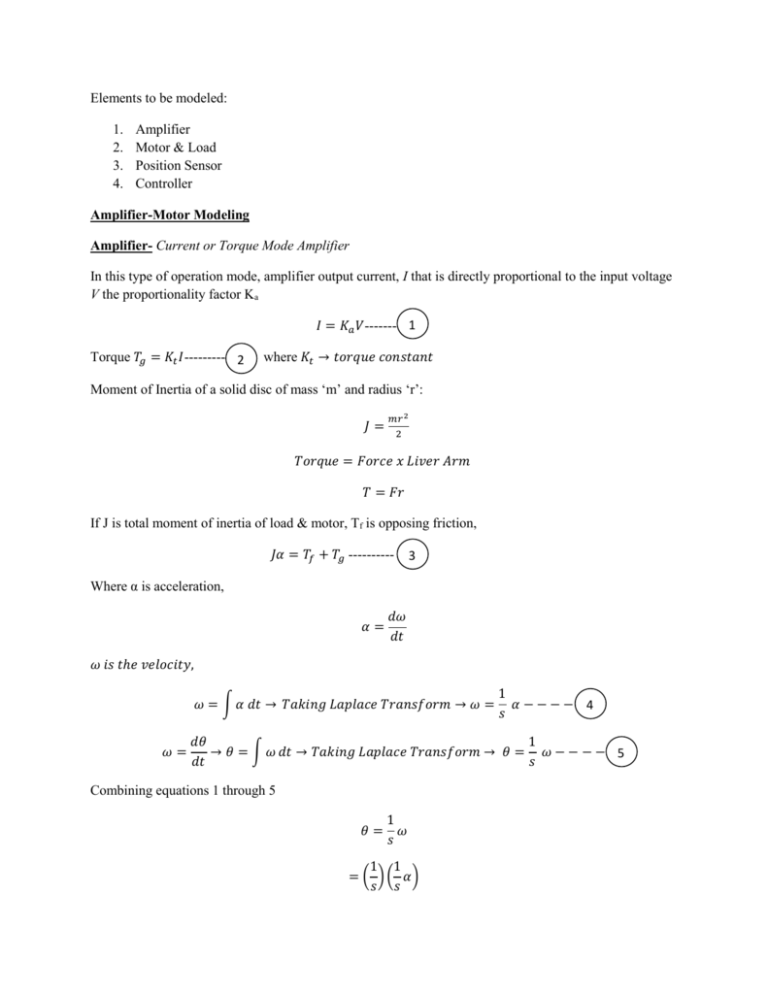
Elements to be modeled: 1. 2. 3. 4. Amplifier Motor & Load Position Sensor Controller Amplifier-Motor Modeling Amplifier- Current or Torque Mode Amplifier In this type of operation mode, amplifier output current, I that is directly proportional to the input voltage V the proportionality factor Ka 𝐼 = 𝐾𝑎 𝑉------- 1 Torque 𝑇𝑔 = 𝐾𝑡 𝐼--------- 2 where 𝐾𝑡 → 𝑡𝑜𝑟𝑞𝑢𝑒 𝑐𝑜𝑛𝑠𝑡𝑎𝑛𝑡 Moment of Inertia of a solid disc of mass ‘m’ and radius ‘r’: 𝐽= 𝑚𝑟 2 2 𝑇𝑜𝑟𝑞𝑢𝑒 = 𝐹𝑜𝑟𝑐𝑒 𝑥 𝐿𝑖𝑣𝑒𝑟 𝐴𝑟𝑚 𝑇 = 𝐹𝑟 If J is total moment of inertia of load & motor, Tf is opposing friction, 𝐽𝛼 = 𝑇𝑓 + 𝑇𝑔 ---------- 3 Where α is acceleration, 𝛼= 𝑑𝜔 𝑑𝑡 𝜔 𝑖𝑠 𝑡ℎ𝑒 𝑣𝑒𝑙𝑜𝑐𝑖𝑡𝑦, 𝜔 = ∫ 𝛼 𝑑𝑡 → 𝑇𝑎𝑘𝑖𝑛𝑔 𝐿𝑎𝑝𝑙𝑎𝑐𝑒 𝑇𝑟𝑎𝑛𝑠𝑓𝑜𝑟𝑚 → 𝜔 = 𝜔= 1 𝛼−−−− 4 𝑠 𝑑𝜃 1 → 𝜃 = ∫ 𝜔 𝑑𝑡 → 𝑇𝑎𝑘𝑖𝑛𝑔 𝐿𝑎𝑝𝑙𝑎𝑐𝑒 𝑇𝑟𝑎𝑛𝑠𝑓𝑜𝑟𝑚 → 𝜃 = 𝜔 − − − − 5 𝑑𝑡 𝑠 Combining equations 1 through 5 1 𝜃= 𝜔 𝑠 1 1 = ( ) ( 𝛼) 𝑠 𝑠 = 1 𝑇𝑔 𝑠2 𝐽 𝑖𝑓 𝑇𝑓 𝑖𝑠 𝑛𝑒𝑔𝑙𝑒𝑐𝑡𝑒𝑑 →= 𝜃= 1 𝐾𝑡 𝐼 𝑠2 𝐽 1 𝐾𝑎 𝐾𝑡 𝑉 𝑠2 𝐽 𝜃 𝐾𝑎 𝐾𝑡 = −−−− 6 𝑉 𝐽𝑠 2 Position Sensor Modeling Motor position is indicated by position sensor as signal ‘c’. Kf proportionality factor, Kf equals the number of units of feedback per one radian of rotation. Encoder provides the position, suppose an incremental encoder generates N pulses per revolution, that the encoder generates output. Channels A & B produces 1000 pulses for each encoder rotation. As two signals are shifted by one quarter of a cycle, the controller can divide each encoder cycle into four quadrant counts resulting in an effective resolution of 4N counts per revolution or turn. Since each revolution is 2π radians, the resulting encoder gain is 𝐾𝑓 = 4𝑁 -2𝜋 7 Model for Incremental Encoder: 𝐾𝑓 = = 4𝑁 −− 7 2𝜋 4 𝑥 1000 𝑐𝑜𝑢𝑛𝑡𝑠 = 636.537 2𝜋 𝑟𝑒𝑣 Thus, 1000 pulse per rev encoder has an equivalent gain of 636 counts/ revolution. Another common type of position sensor is the one of binary representation. Total number of positions per revolution is 2𝑛 the model for this sensor is: 𝐾𝑓 = 2𝑛 − − − −8 2𝜋 For example- For Absolute encoder or resolver with 16-Bit binary position signal has a gain of: 𝐾𝑓 = 216 = 10,435 𝑐𝑜𝑢𝑛𝑡𝑠/𝑟𝑎𝑑𝑖𝑎𝑛𝑠 2𝜋 When a sensor is linear, if the resolution of a sensor is 1 micron and if the length is measured in meters, the encoder gain equals 106 𝑐𝑜𝑢𝑛𝑡𝑠/𝑚𝑒𝑡𝑒𝑟. Modeling a Controller The desired position signal is R(t) or simply ‘R’ actual position is ‘C’. Thus position error ‘E’: 𝐸 =𝑅−𝐶 This position error is used to generate the output signal that drives the motor. The proportional term xp , 𝑥𝑝 = (𝑃)(𝐸) Gain of the proportional part of the controller Error, input The derivative term xd , 𝑥𝑑 = (𝑠𝐷)(𝐸) Gain of derivative controller Error, input The integral term xi , 1 𝑥𝑖 = ( 𝐼) 𝐸 𝑠 Gain of the Integral controller Error, input Sum of all three outputs, 𝑥 = 𝑥𝑝 + 𝑥𝑑 + 𝑥𝑖 The Transfer function F(s), relating the output ‘x’ to position error E is, 𝐹(𝑠) = 𝑥 1 = 𝑃 + 𝑠𝐷 + 𝐼 − − − − − 𝑃𝐼𝐷 𝐶𝑜𝑛𝑡𝑟𝑜𝑙𝑙𝑒𝑟 𝐸 𝑠 Digital to Analog converter resolution, 8-16 bit. DAC having output voltage range -10 V to +10 V: Output- -10 V to +10 V Gain of DAC ‘K’, equal to the number of volts it produces per unit of ‘x’ input signal. DAC Resolution in ‘n’ bits, the DAC Gain equals: A 12-Bit DAC has K=0.0048 V/unit 𝐾= 20 20 = = 0.0048 𝑉/𝑢𝑛𝑖𝑡 2𝑛 212 𝑇𝑔 𝐽𝛼 = 𝑇𝑔 𝑜𝑟 𝛼 = 𝐽 1 𝜔= 𝛼 𝑠 1 𝜃= 𝜔 𝑠 𝜃= 11 𝛼 𝑠𝑠 𝜃= 1 𝑇𝑔 𝑠2 𝐽 = = 1 𝐾𝑡 𝐼 𝑠2 𝐽 1 𝑉 𝐾𝑡 𝐾𝑎 2 𝑠 𝐽 𝜃 1 𝐾𝑡 𝐾𝑎 = 2 𝑉 𝑠 𝐽 𝜔 𝐾𝑡 = 2 ∪ 𝑠 𝐽𝐿 + 𝑠𝐽𝑟 + 𝐾𝑒 𝐾𝑡 Encoder Gain: 𝐾𝑓 = 2𝜋 Kf 4𝑁 2𝜋 4N 4 𝑥 1000 ( ) = 636 𝑐𝑜𝑢𝑛𝑡𝑠/𝑟𝑎𝑑 (2)(3.1428)
