DLA Tutorial.docx
advertisement
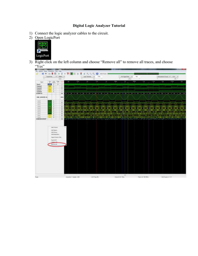
Digital Logic Analyzer Tutorial 1) Connect the logic analyzer cables to the circuit. 2) Open LogicPort 3) Right click on the left column and choose “Remove all” to remove all traces, and choose “Yes” 4) To add signals, right click on the gray portion of the display, and choose “Add Signal…” 5) What will pop up is a list of inputs that you can choose from to display on the screen: On the left, you will see “D0, D1, …”. The background color corresponds to the tip of each wire, while the color of the text corresponds to the main wire color itself. 6) To change the names of the signals, you can right click and choose “Edit Signals…” 7) You will then need to select the signals and add them to what you are analyzing. 8) Under options -> Trigger, select the trigger to “Immediately when acquisition starts”. 9) In the main screen you can set “Sample Rate” to 100MHz, “logic threshold” to something that should clearly be a logic high, like 3.00v, and leave the rest as default. 10) To start capturing data, click the “Single Acquisition” button on the main toolbar. For continuous captures, select “Recurring Acquisition” right next to it. 11) Be sure that your zoom is correct (you might have to zoom out to see a whole trace). 12) To make a screen capture, select File->Print to clipboard and save it in Word or Paint.


