Operating instructions
advertisement
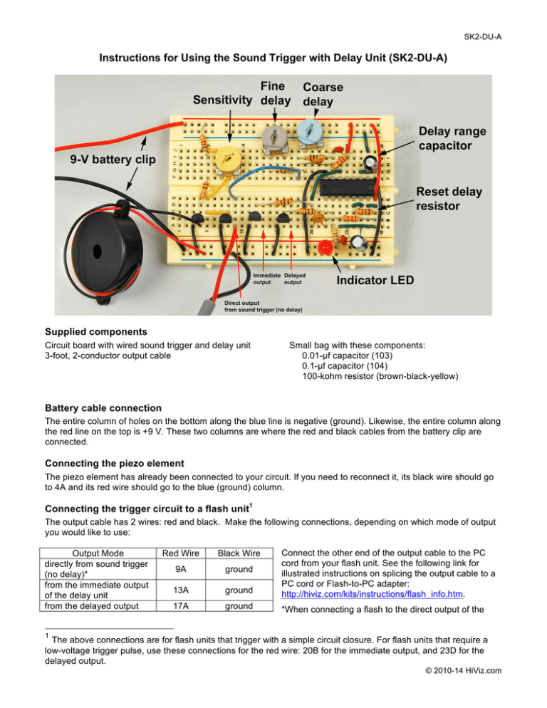
SK2-DU-A Instructions for Using the Sound Trigger with Delay Unit (SK2-DU-A) Supplied components Circuit board with wired sound trigger and delay unit 3-foot, 2-conductor output cable Small bag with these components: 0.01-µf capacitor (103) 0.1-µf capacitor (104) 100-kohm resistor (brown-black-yellow) Battery cable connection The entire column of holes on the bottom along the blue line is negative (ground). Likewise, the entire column along the red line on the top is +9 V. These two columns are where the red and black cables from the battery clip are connected. Connecting the piezo element The piezo element has already been connected to your circuit. If you need to reconnect it, its black wire should go to 4A and its red wire should go to the blue (ground) column. Connecting the trigger circuit to a flash unit1 The output cable has 2 wires: red and black. Make the following connections, depending on which mode of output you would like to use: Output Mode directly from sound trigger (no delay)* from the immediate output of the delay unit from the delayed output Red Wire Black Wire 9A ground 13A ground Connect the other end of the output cable to the PC cord from your flash unit. See the following link for illustrated instructions on splicing the output cable to a PC cord or Flash-to-PC adapter: http://hiviz.com/kits/instructions/flash_info.htm. 17A ground *When connecting a flash to the direct output of the 1 The above connections are for flash units that trigger with a simple circuit closure. For flash units that require a low-voltage trigger pulse, use these connections for the red wire: 20B for the immediate output, and 23D for the delayed output. © 2010-14 HiViz.com SK2-DU-A sound trigger, first disconnect the wire from the output of the trigger to the input of the delay unit (9E to 18 F). If this wire is left in place, some flash units can burn out the 556 timer. Connecting the output cable to a camera or wireless trigger If you wish to trigger either a wireless transmitter or your camera shutter instead of a flash unit, see this page: http://hiviz.com/kits/instructions/camera_wireless_info.htm. Powering the unit The circuit runs on a 9-V battery. Connect the wires from the battery clip to the +9 V and ground columns. Disconnect the battery when the circuit is not in use. You may also choose to use a 9-V AC/DC adapter to power the unit. Any AC/DC adapter that provides up to an ampere of direct current at 9 V should do. Here’s an example: http://hiviz.com/kits/ACDC_adapter.htm. Connecting the trigger to the delay unit The jumper wire connecting the sound trigger to the delay unit runs from 9E (sound trigger output) to 18F (delay unit input). For testing the delay unit without the sound trigger, you can remove the jumper wire from 9E and touch it momentarily to ground. The red LED should light if momentarily if the delay unit is working correctly. Adjusting the delay time The 1M potentiometer (blue knob) provides coarse delay control. Rotate it clockwise to increase the delay time up to about half a second. The 100k potentiometer (brown knob) provides fine delay control. Set the coarse delay first and then tune it with the fine delay. Adjusting sensitivity Connect a flash unit to the direct output of the sound trigger (9A to ground). Turn the 1k potentiometer (yellow knob) about three-quarters of the way clockwise for a typical setting. You may find that when you’re using an output of the delay unit, the knob must be turned further clockwise. Changing the delay range by switching capacitors A half second delay is long for many high-speed photography situations. You can change the delay by replacing the 0.47-µf capacitor with one of smaller value. Extra 0.1-µf and 0.01-µf capacitors have been provided for this purpose, and will yield the following time delays. Capacitor 0.47-µf (cylindrical) 0.1-µf (labeled “104”) 0.01-µf (labeled “103”) Time Delay Half second Up to ~1/10 second Up to ~1/100 second Location (+) to 28I, (-) to 29H 28I-29H (nonpolar) 28I-29H (nonpolar) Replacing the 1-kohm resistor with a 100-kohm resistor to increase the reset delay The 1-kohm resistor from 26C to 29C can be replaced with the extra 100-kohm resistor in order to increase the dead time after a triggering event. During this dead time, the circuit won’t trigger. This is useful to prevent secondary events such as a second drop from actuating the circuit. The dead time is approximately equal to the value of the resistor in kilohms divided by 100. For example, the dead time for a 100-kohm resistor would be 1 second. Replacing components Due to the nature of an open circuit on a breadboard, components may become dislodged and need to be reseated. Complete instructions for component placement can be found at the link below. http://hiviz.com/kits/instructions/sk2-du-manual2.htm © 2010-14 HiViz.com

