Document 14435860
advertisement
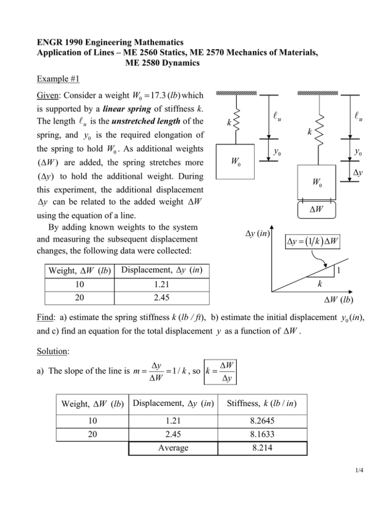
ENGR 1990 Engineering Mathematics Application of Lines – ME 2560 Statics, ME 2570 Mechanics of Materials, ME 2580 Dynamics Example #1 Given: Consider a weight W0 = 17.3 (lb) which is supported by a linear spring of stiffness k. The length A u is the unstretched length of the Au k Au k spring, and y0 is the required elongation of the spring to hold W0 . As additional weights (ΔW ) are added, the spring stretches more y0 y0 W0 Δy ( Δy ) to hold the additional weight. During W0 this experiment, the additional displacement Δy can be related to the added weight ΔW ΔW using the equation of a line. By adding known weights to the system and measuring the subsequent displacement changes, the following data were collected: Weight, ΔW (lb) Displacement, Δy (in) 10 20 1.21 2.45 Δy (in) Δy = (1 k ) ΔW 1 k ΔW (lb) Find: a) estimate the spring stiffness k (lb / ft), b) estimate the initial displacement y0 (in), and c) find an equation for the total displacement y as a function of ΔW . Solution: a) The slope of the line is m = Δy ΔW = 1 / k , so k = ΔW Δy Weight, ΔW (lb) Displacement, Δy (in) 10 20 Stiffness, k (lb / in) 1.21 2.45 8.2645 8.1633 Average 8.214 1/4 An estimate of the spring stiffness is the average derived from the two measurements. ⎡ 8.214 (lb) ⎤ ⎡12 (in) ⎤ Units change: k = ⎢ ⎥×⎢ ⎥ = 98.57 (lb / ft ) ⎢⎣ (in) ⎥⎦ ⎢⎣ ( ft ) ⎥⎦ b) The initial displacement y0 may be found by noting that the initial displacement and weight are related by the same stiffness. y0 = W0 / k = 17.3 (lb) / 8.214 (lb / in) = 2.106 (in) c) The equation for the total displacement can be found using the slope-intercept form of the line. y = 2.106 + (1 8.214)ΔW = 2.106 + (0.1217) ΔW Example #2 Given: Consider a long slender beam of length L with a concentrated load P acting at distance a from the left end. Due to this load, the beam experiences an internal bending moment M that varies linearly across the length of the beam as shown. The maximum bending moment M max occurs at the load. Y P a b X L M In an experiment, a load P = 100 (lbs ) is applied to a beam of length L = 5 ( ft ) . The bending moments measured at two points on either side of P are Location, x ( ft ) Moment, M ( ft - lb) 2.067 4.378 64.3 42.87 X a L Location Relative to Load left of load right of load 2/4 Find: a) the moment equations for 0 ≤ x ≤ a and a ≤ x ≤ L ; b) the location of the load P ; and c) the maximum moment experienced by the beam. Solution: a) For 0 ≤ x ≤ a , the slope of the line is m = ( 64.3 − 0 ) ( 2.067 − 0 ) = 31.11 , so M ( x ) = mx = 31.11 x (1) For a ≤ x ≤ L , the slope of the line is m = ( 0 − 42.87 ) ( 5 − 4.378) = −68.92 . Using the point-slope form of a line, we can write ( M − 42.87 ) = −68.92 ( x − 4.378) ⇒ M = ( 42.87 + (68.92 × 4.378) ) − 68.92 x or M ( x) = 344.6 − 68.92 x (2) b) The load P is located at the point x = a where the moment equations (1) and (2) are equal, that is, at the intersection of the two lines. To find a , set 31.11x = 344.6 − 68.92 x ⇒ ( 31.11 + 68.92 ) x = 344.6 or a = 344.6 ( 31.11 + 68.92 ) = 3.445 ( ft ) (3) c) The maximum moment experienced by the beam may be calculated by substituting the value of a into equations (1) or (2). M max = M ( a ) = 31.11 × 3.445 = 107.2 ( ft - lb) or M max = M (a) = 344.6 − ( 68.92 × 3.445) = 107.2 ( ft - lb) 3/4 Bending Moment (ft‐lb) 120 3.445, 107.2 Moment (ft‐lb) 100 80 2.067, 64.3 60 4.378, 42.87 40 20 0 0, 0 0 5, 0 1 2 3 4 5 x (ft) 4/4


