OPTIMIZING A THERMOELECTRIC GENERATOR FOR THE DYNAMIC THERMAL ENVIRONMENT
advertisement
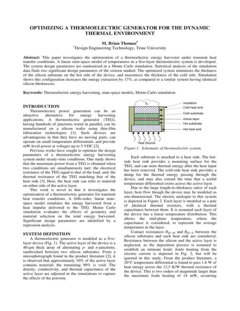
OPTIMIZING A THERMOELECTRIC GENERATOR FOR THE DYNAMIC THERMAL ENVIRONMENT M. Brian Thomas1 1 Design Engineering Technology, Trine University Abstract: This paper investigates the optimization of a thermoelectric energy harvester under transient heat transfer conditions. A linear state-space model of temperatures in a five-layer thermoelectric system is developed. The system design parameters are randomized in a Monte Carlo simulation. Statistical analysis of the simulation data finds two significant design parameters of the sixteen studied. The optimized system minimizes the thickness of the silicon substrate on the hot side of the device, and maximizes the thickness of the cold side. Simulation shows this configuration increases the energy extraction by 17%, as compared to a similar system having identical silicon thicknesses. Keywords: Thermoelectric energy harvesting, state-space models, Monte Carlo simulation INTRODUCTION Thermoelectric power generation can be an attractive alternative for energy harvesting applications. A thermoelectric generator (TEG), having hundreds of junctions wired in parallel, can be manufactured on a silicon wafer using thin-film fabrication technologies [1]. Such devices are advantageous in that they have no moving parts, can operate on small temperature differentials, and provide mW-level power at voltages up to 5 VDC [2]. Previous works have sought to optimize the design parameters of a thermoelectric energy harvesting system under steady-state conditions. One study shows that the maximum power from a TEG is obtained when two conditions are simultaneously met: the electrical resistance of the TEG equal to that of the load, and; the thermal resistance of the TEG matching that of the heat sink [3]. Here, the heat sink can refer to material on either side of the active layer. This work is novel in that it investigates the optimization of a thermoelectric generator for transient heat transfer conditions. A fifth-order, linear statespace model simulates the energy harvested from a heat impulse delivered to the TEG. Monte Carlo simulation evaluates the effects of geometry and material selection on the total energy harvested. Significant design parameters are identified by a regression analysis. SYSTEM DEFINITION A thermoelectric generator is modeled as a fivelayer device (Fig. 1). The active layer of the device is a 40-ȝm thick array of alternating p- and n-junctions, sandwiched between two silicon substrates. From a microphotograph found in the product literature [2], it is observed that approximately 10% of the active layer contains material; the remaining 90% is void. The density, conductivity, and thermal capacitance of the active layer are adjusted in the simulations to capture the effects of the porosity. Figure 1. Schematic of thermoelectric system. Each substrate is attached to a heat sink. The hotside heat sink provides a mounting surface for the TEG, and can store thermal energy after the heat input has been removed. The cold-side heat sink provides a dump for the thermal energy passing through the device, and may also extend the time that a useful temperature differential exists across the active layer. Due to the large length-to-thickness ratios of each layer, heat flow though the device may be modeled as one-dimensional. The electric analogue to this system is depicted in Figure 2. Each layer is modeled as a pair of identical thermal resistors, with a thermal capacitance between them. It is assumed each layer of the device has a linear temperature distribution. This allows the mid-plane temperature, where the capacitance is considered, to represent the average temperature in the layer. Contact resistances ܴுିௌ and ܴௌି between the silicon substrates and each heat sink are considered. Resistance between the silicon and the active layer is neglected, as the deposition process is assumed to establish an intimate bond. Joule heating from the electric current is depicted in Fig. 2, but will be ignored in this study. From the product literature, a 20°C temperature differential is found to pass 1.6 W of heat energy across the 12.5 K/W thermal resistance of the device. This is two orders of magnitude larger than the maximum Joule heating of 14 mW, occurring ܳா்ିு ൌ ܳଵଶ ܳଵ &ROGKHDW VLQN ଵଶ represents the heat flowing from node 1 to node 2, and ଵ , the heat applied towards changing the temperature of the hot heat sink. Using linear thermal elements, Eq. (7) is expressed as, &ROG VXEVWUDWH ܳா்ିு ൌ $FWLYH OD\HU (7) ሺܶଵ െ ܶଶ ሻ ൗܴ ܥு ܶଵሶ ଶ (8) Rearranging Eq. (8) yields an explicit expression for the temperature rate. ܳ െܶ ܶ ܶଵሶ ൌ ா்ିுൗ ܥ ଵൗܴ ܥ ଶൗܴ ( ܥ9) ு ଶ ு ଶ ு RTE/2 RTE/2 +RWVXEVWUDWH This procedure is repeated to find the other state temperature rates. Combining these equations yields a linear state-space model having the form, ܂ሶ ൌ ۯȉ ܂ ۰ ȉ ܃ (10) +RWKHDW VLQN where, ܂ൌ ሾܶଵ Figure 2. Electric analog of thermoelectric system. when the TEG generates a 5.8 mA current at 2.35 V to a matched electric load of 400ȍ. State temperatures ܶଵ through ܶହ are established at the mid-plane points of each layer. Thermal resistances ܴଵ through ܴ are obtained by summing the thermal resistance elements between adjacent state temperatures. ܴଵ ൌ ܴுൗ ʹ (1) ܴଶ ൌ ܴுൗ ܴௌଵൗ ʹ ܴுିௌ ʹ (2) ܴଷ ൌ ܴௌଵൗ ்ܴாൗ ʹ ʹ (3) ܴସ ൌ ்ܴாൗ ܴௌଶൗ ʹ ʹ (4) ܴଶ ൌ ܴௌଶൗ ܴ ʹ ܴௌି ൗʹ (5) ܴ ൌ ܴൗ ʹ ܴିா் (6) Conservation of energy may be used to determine the state equations. Balancing the heat energy flow at the ܶଵ node, ۍ ێ ۰ൌێ ێ ێ ۏ ܶଶ ͳൗ ܥு Ͳ Ͳ Ͳ Ͳ ܶଷ ܶସ ܶହ ሿ் (11) Ͳ ې ۑ ۑ ۑ ۑ ͳൗ ܴ ܥு ے (12) ܶா்ǡ ሿ (13) Ͳ Ͳ Ͳ and, ܃ൌ ሾܳா்ǡு The system A matrix is defined in Equation (14). Note that this system model can approximate the cold-side heat sink being insulated by assigning to ܴ a value several orders of magnitude larger than the other resistances. The system response to a one-second, 1.0-Watt heat pulse applied to the hot heat sink is simulated using the lsim command in MATLAB. The time vector used here has a resolution of 0.05 seconds, and is 100 seconds long as to measure energy harvested after the heat pulse. The cold heat sink is treated as being insulated. The accuracy of the linear state-space model is established by comparing its predictions to those from a finite element model (FEM). The system under consideration is a cylinder having a 1.0-mm radius. It consists of five 0.8-mm-thick layers: copper, lead, Pyrex, lead, and copper. One face of the cylinder is exposed to a 200 ms, 1-Watt heat pulse; the other surfaces are insulated. The FEM representation of this system is modeled as a 2-D, axisymmetric body. Existing MATLAB code for transient heat flow in ିଵ ୖ ۍమ େ ౄ ێଵ ୖێమ େభ ێ ۯൌͲ ێ ێ Ͳ ێ ێ Ͳ ۏ ଵ ୖమ େౄ ିଵ ଵ ቀ େభ ୖమ ଵ Ͳ ଵ ୖయ ଵ ቁ ୖయ େు Ͳ Ͳ Ͳ ିଵ ୖయ େభ ଵ ଵ ቀ େు ୖయ ଵ ୖర ୖర େమ Ͳ ቁ Ͳ ې ۑ Ͳ Ͳ ۑ ۑ ଵ Ͳ ۑ ୖర େు ۑ ିଵ ଵ ଵ ଵ ቀ ቁ ۑ େమ ୖర ୖఱ ୖఱ େమ ଵ ିଵ ଵ ଵ ۑ ቀ ୖ ቁے ୖఱ େి େి ୖఱ ల (14) axisymmetric bodies is applied [4, 5]. A comparison of the state-space model and the FEM shows excellent agreement in the predicted midplane temperature profiles. The temperature response of the Pyrex in the state-space model, though, lags that of the FEM. This is attributed to the lower thermal diffusivity of Pyrex with respect to copper and lead. A nonlinear temperature distribution in the Pyrex layer is observed in the FEM, which violates the assumption of a linear temperature distribution in the state-space model. Still, the state-space model is expected to provide qualitatively correct results for this study. The principle benefit of the state space model is that a dynamic response may be computed in MATLAB in under a second, while the FEM requires hours to simulate the same system. calculated for each iteration. Linear regression finds the coefficient of determination, R2, between the energy harvested and each of the random parameters. R2 is calculated over each set of 300 iterations as well as for the entire set of 2700 iterations. MONTE CARLO SIMULATION Hot heat sink Monte Carlo simulation is a process in which the effects of selected parameters on a system’s outputs can be evaluated by randomizing the parameters over multiple iterations. Here, it is applied towards optimizing the energy harvested by a TEG under transient thermal conditions. For the system under consideration, the active layer is based on that of the MPG-751, manufactured by MicroPelt GmbH (Freiburg, Germany). The substrates are constrained to be silicon, but their thickness and cross-section area are allowed to vary. The geometry and the material of each heat sink are also random parameters. The heat sinks are classified as either “metal”, “glass”, or “polymer”. Within each classification, material properties – thermal conductivity, k, heat capacity, c, and density, ȡ – are limited to values consistent with that material. This avoids possible simulation of unobtainable materials. Table 1 shows the limits on geometry by layer; Table 2 shows the limits for material properties by classification. The contact resistance flux between each heat sink and the adjoining silicon is also allowed to vary between 0 and 0.1 m2·K·W-1, representing values found in [6]. Thermal resistances ܴுିௌ and ܴௌି are obtained by multiplying the resistance flux by the contact area. Each iteration of the Monte Carlo simulation contains 16 random parameters. For each permutation of heat sink materials (metal-metal, metal-glass, etc.), 300 iterations are run. The total energy harvested is Table 1. TEG system geometric parameters. Cold heat sink Cold substrate Active layer Hot substrate Thickness: 0.25-5.0 mm Area: 100%-150% of cold silicon Thickness: 0.25-2.0 mm Area: 100%-150% of active layer Thickness: 0.04 mm Area: 11.40 mm2 Thickness: 0.25-2.0 mm Area: 100%-150% of active layer Thickness: 0.25-5.0 mm Area: 100%-150% of hot silicon Table 2. Material property limits for heat sinks. Metal Glass Polymer k c ȡ k c ȡ k c ȡ 100.9-102.6 (7.94-398) W·m-1·K-1 116-1825 J·kg-1·K-1 1740-21450 kg·m-3 10-0.2-100.9 (0.63-7.94) W·m-1·K-1 500-1250 J·kg-1·K-1 2000-4000 kg·m-3 10-1.0-10-0.2 (0.10-0.63) W·m-1·K-1 1000-3000 J·kg-1·K-1 500-2500 kg·m-3 RESULTS Analysis of the Monte Carlo simulation data shows that the thicknesses of the silicon substrates are the most relevant parameters for maximizing the energy harvested. Specifically, the thickness of the hot-side silicon must be minimized, while that of the cold side must be maximized. For the hot-side silicon, R2 ranges from 0.17 and 0.35 within each group of 300 iterations. Over all 2700 iterations, the R2 value is 0.22. Virtually identical results are found for the cold-side substrate, with R2 ranging from 0.17 to 0.35, and a value of 0.23 for the entire data set. Only one other parameter has a coefficient of determination above 0.1 within a set of 300 iterations, but this datum (0.11) is thought to be an outlier. R2 values for the other parameters over all 2700 iterations range from 0.0005 to 0.037. Finite element modeling confirms this finding. A nominal system is established, consisting of an MPG751 generator with two 1.0-mm-thick aluminum heat sinks. The thickness of each silicon layer in the nominal system is 0.525 mm [2]. A variant of this system has a hot-side silicon thickness of 0.2 mm, and a cold-side thickness of 0.825 mm. The total thickness of the device is unchanged. A second variant has thicknesses of 0.825mm and 0.2 mm for the hot- and cold-side substrates, respectively. A one-second, 1Watt heat impulse is again considered. Figure 3 shows the power output from the TEG as predicted by the linear state-space model. Thinning the hot-side substrate and thickening of the cold-side substrate improves the peak power by 29%. Figure 4 shows the same system as simulated by the FEM. The results are similar, but the gain in peak power only 17%, less than the gain realized by the state-space model. 5.0 Power (mW) 4.0 3.0 2.0 1.0 0.0 0.0 1.0 2.0 model. As observed earlier, transient conditions can result in nonlinear temperature distributions that conflict with the assumptions supporting a state-space model. While individual elements in the FEM have linear temperature distributions, the fact that there are more elements provides a higher resolution for temperature along the direction of heat flow. The FEM used in this study also captures two-dimensional heat flow effects, which are ignored in the state-space model. CONCLUSIONS Monte Carlo simulation and statistical analysis is applied towards optimizing thermoelectric energy harvesting in the transient thermal environment. Under the conditions studied, the energy extracted by a TEG is maximized when the hot-side silicon substrate is thin, and the cold-side substrate is thick. A thinner hotside substrate is thought to increase the response speed of the active layer due to rapid heating of the substrate. Conversely, a thicker cold-side substrate is thought to be more effective as a sink for the heat flowing through the device. By keeping the cold junctions cold, a temperature differential can be sustained across the active layer. The scope of this paper is limited in that it considers only a single configuration for boundary conditions. Future study should work towards generalizing the findings for a broader set of thermal environments. Obtaining experimental verification of the theoretical findings is another goal for this author. 3.0 REFERENCES Time (s) [1] Si thickness equal Hot Si thin; Cold Si thick Hot Si thick; Cold Si thin Figure 3. Power predicted by state-space models. [2] 5.0 [3] Power (mW) 4.0 3.0 2.0 [4] 1.0 0.0 0.0 1.0 2.0 3.0 Time (s) [5] Si thickness equal Hot Si thin; Cold Si thick Hot Si thick; Cold Si thin [6] Figure 4. Power predicted by finite-element models. It is thought that the FEM model provides a better representation of the actual system than the state-space Böttner H 2005 Micropelt Miniaturized Thermoelectric Devices: Small Size, High Cooling Power Densities, Short Response Time International Conference on Thermoelectrics 2005 (19-23 June 2005) 1-8 2008 MPG-D602, MPG-D751 Thin Film Thermogenerators and Sensing Devices, Micropelt GmbH (Freiburg Germany). Bierschenk J L 2009 Optimized Thermoelectrics for Energy Harvesting Applications Energy Harvesting Technologies (New York, Springer Science+Business Media) 337-351 Thomas M B 2009 Thermoelectric Energy Harvesting in Small-Caliber Projectiles Technical Digest PowerMEMS 2009 (Washington DC, USA, December 1-4 2009) 261-264 Thomas M B and Dozier L 2010 Finite element modeling of transient temperatures in a smallcaliber projectiles Amer. J. Applied Science Engr. 3 (2) 355-362 Incropera F P 2002 Fundamentals of Heat and Mass Transfer 6 ed. (New York, John Wiley & Sons)
