Supporting Information
advertisement
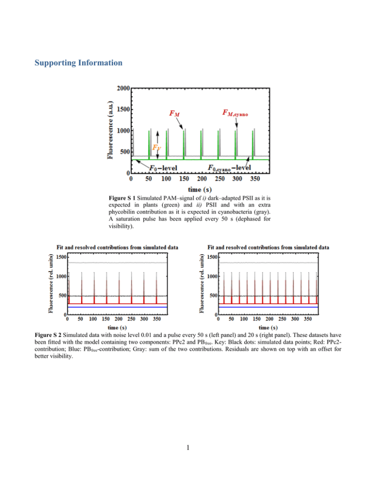
Supporting Information Figure S 1 Simulated PAM–signal of i) dark–adapted PSII as it is expected in plants (green) and ii) PSII and with an extra phycobilin contribution as it is expected in cyanobacteria (gray). A saturation pulse has been applied every 50 s (dephased for visibility). Figure S 2 Simulated data with noise level 0.01 and a pulse every 50 s (left panel) and 20 s (right panel). These datasets have been fitted with the model containing two components: PPc2 and PB free. Key: Black dots: simulated data points; Red: PPc2contribution; Blue: PBfree-contribution; Gray: sum of the two contributions. Residuals are shown on top with an offset for better visibility. 1 On the relationship between Chl a fluorescence and photochemistry. Three essential assumptions are made in order to use fluorescence as a proxy for photosynthetic activity. First, harvested light has three possible pathways: either it reaches the reaction centers of PSII where it is used for photochemistry (ph) or it gives rise to fluorescence (fl) or it gets dissipated as heat (h): ph fl h 1 (S1) Second, a saturation–pulse induces a state where QA is reduced, i.e. transient saturation of PSII (closed centers), while the fluorescence and heat dissipation yields are maximal: ( fl ) M ( h ) M 1 (S2) And last, the ratio of the fluorescence and heat dissipation yields is assumed not to vary during the saturating pulse: h ( h ) M fl ( fl ) M (S3) Therefore, combining Eq. (S2) and (S3) we obtain an expression for (h)M that can be replaced in Eq. (S1) so that the yield of photochemistry is strictly related to the one of fluorescence: fl ( fl ) M fl ph 1 fl fl ( ) ( fl ) M fl M (S4) This relationship has propelled numerous studies aiming to track fluorescence under controlled light conditions and relate those measurements to the PSII photochemical yield. The parameter: FV F F0 M FM FM (S5) directly derived from Eq.(S4), has been commonly equaled to the index of maximal photochemical efficiency of PSII in plant studies. We therefore obtain (see Eqs. Error! Reference source not found.& Error! Reference source not found.): cyano FM ,cyano F0,cyano FM ,cyano FM ,PSII F0,PSII FM ,PSII F0,PB (S6) Hence, for a fixed level of Chl a (PSII) fluorescence, the cyanobacterial cyano decreases with increasing phycobilisome/Chl ratio or disconnected PBs/PSII (for an example under Fe starvation see Wilson et al. 2007). Figure S 3 illustrates Eq. (S6). Note that this decrease is not related to a change in photochemistry. Thus, without knowing how much the PB contributes to the signal, the parameter FV/FM cannot be used to measure the maximal photochemical efficiency of PSII. In addition, when performed 2 in plants, these measurements are done in darkness, conditions in which there is no NPQ. In contrast, cyanobacterial cells tend to state 2 in darkness Campbell et al. 1998; as a consequence FM is quenched. Figure S 3 Normalized expression for cyanobacterial cyano (with respect to plants) as a function of the phycobilin-related contribution F0,PB. Using Eq. Error! Reference source not found. we can re-write Eq.(S6): cyano c2 (PPc 2,c,u PPc 2,o,u ) c2 PPc 2,c,u PB ,u (S7) with: c2 1 3 (S8) Figure S 4 cyano as a function of the relative concentration of PB free and the difference of PPc2 quantum yields in open and closed states. Two curves have been plotted for two distinct values of PPc2,o,u while PPc2,c,u has been kept constant. The graph illustrates how the variable fluorescence decreases with decreasing contrast between open and closed states:PSII=PPc2,c,u – PPc2,o,u. Key: Black: PSII=0.34; Blue:PSII=0.18. Derivation of the quenching and recovery dynamics. Formation of a quenching complex C q . The homogeneous system. The system of second order differential equations describing the formation of a quenching complex Cq from an activated OCPr that binds to a PB is: PB'(t) k1 PB(t) OCPr (t) k 2 Cq (t) (S9) OCPr '(t) k1 PB(t) OCPr (t) k2 Cq (t) (S10) Cq'(t) k1 PB(t) OCPr (t) k 2 Cq (t) (S11) where the product PB(t)·OCPr(t) accounts for the encounter probability between a photoactivated OCP and a PB. Note that PB’(t) = OCPr’(t) = – Cq’(t). This property allows the system to be simplified and expressed in terms of the single variable PB(t). After subtraction of Eq. (S9) from Eq. (S10) we obtain the homogeneous equation: 4 OCP '(t) PB'(t) dt 0 r (S12) from which it follows that the general solution is: OCPr (t) PB(t) a1 (S13) where a1 is an arbitrary constant. We obtain the value of a1 by simply evaluating both functions at time t=0. Thus: a1 OCP r 0 PB0 (S14) Replacing Eq. (S14) in Eq. (S13) yields an expression of OCPr(t) as a function of PB(t) given some starting values for the PB and photoactivated form of OCP at time t=0: OCP r (t) PB(t) PB0 OCP r 0 (S15) Furthermore, adding Eq. (S9) to Eq. (S10) leads to a row of equations similar to Eqs.(S11)–(S15) in the case of the quenching complex Cq(t). We obtain the final expression: C q (t) PB(t) PB0 Cq ,0 (S16) By inserting Eqs. (S15) & (S16) in Eq. (S11) we finally obtain a single equation of second order for the single variable PB(t). Its graphical solution is shown in Figure S 5A : PB'(t) k1 PB2 (t) k1 (PB0 OCPr 0 ) k2 PB(t) k2 (PB0 Cq,0 ) 5 (S17) A: Parameters: k1=0.025; k2=0.001; OCPr0=0.5; OCPo0=0 B: Parameters: k1=0.025; k2=0.001; OCPr0=0; OCPo0=0.5 C: Parameters: k1=0.025; k2=0.01; OCPr0=0; OCPo0=0.5 D: Parameters: k1=0.025; k2=0.001; OCPr0=0; OCPo0=0.33 Figure S 5 Graphical solutions shown for a homogeneous (A) and an inhomogeneous (B–D) system of differential equations reproducing the NPQ-dynamics over time. In all panels: [PB0]=1, [Cq]=0. In panels B–D: I=0.1, k3=0.05. Key: blue: Qu; red: Qr; green: Qq; orange: Qo (see text for explanation). 6 The light-intensity dependent generation of OCP r . The inhomogeneous system. The observed kinetics up to now imply a non–zero concentration of OCPr at time t=0 (note OCPr0=0.5 in Figure S 5A). This is, however, far from the experimental observation: OCP has to be photo–converted by light absorption from its orange to its red form first. This process depends on the wavelength and intensity of the light. The time–dependent generation of OCPr from the orange form of a fixed amount of OCPo will therefore be introduced as an inhomogeneity in Eq. (S12) with I being the light-intensity dependent formation rate of OCPr: OCP '(t) PB'(t) dt r I OCPo 0 e I t dt (S18) which once integrated and evaluated at time t=0 (for the left side of the equation we know the answer already from Eq. (S13)): a1 OCPo0 e I t t 0 a2 (S19) yields the constant a2 = a1 + OCPo0 and we obtain thus the solution for all times t: OCPr (t) PB(t) PB0 OCPr 0 OCPo0 1 eI t (S20) An analogous equation to Eq. (S17) can now therefore be derived by inserting Eq. (S20) instead of Eq. (S15) in Eq. (S9) (see Eq. (S21)). Finally, we introduce a last kinetic parameter, namely a deactivation rate of OCPr k3 that accounts for the fact that the population OCPo grows as OCPr deactivates. The system of differential equations we need to solve reads: PB'(t) k1 PB2 (t) k1 PB0 OCPr 0 OCPo0 OCPo (t) k2 PB(t) k2 (Cq,0 PB0 ) OCPo'(t) I OCPo (t) k3 PB(t) PB0 OCPr 0 OCPo0 OCPo (t) (S21) (S22) A solution to this system can only be given numerically. The graphical solution of this quenching function which we call Qi(P,t) is shown in Figure S 5 for a chosen set P of parameters. Qi(P,t) has four components: Qu (blue) describes de unquenched PB, Qq (green) the quenching complex Cq, Qo (orange) the orange form of OCP and Qr its photo–converted red form. Notice that this time OCPr0=0 while OCPo0=0.5. The deactivation rate of OCPr k3 has been chosen to be smaller (k3=0.05) than the activation rate (I=0.1). 7 The recovery phase. Turning off the actinic light simply translates in setting the parameter I to zero. Furthermore, we assume that during the quenching phase only a fraction of the orange OCP is converted to its red form. The graphical solution of the recovery phase with two different sets of parameters (k2 is varied) is shown in Figure S 6. A: Parameters: I=0; k2=0.001 B: Parameters: I=0; k2=0.005 Figure S 6 Graphical solution for the recovery dynamics (I=0) with k2=0.001 (A) and k2=0.005 (B). Parameters: PB0=0.55; Cq,0=0.45; OCPr0=0.1; OCPo0=0.001; k1=0.025; k3=0.05. Key: blue: Qu; red: Qr; green: Qq; orange: Qo NPQ Model applications Light-dependent OCPo→OCPr conversion. The NPQ dynamics in the cyanobacterium Synechocystis has been studied by Gorbunov et al. 2011. In Fig. 3B of their publication they show how NPQ is differently induced when varying the ambient light intensity. We have digitized their data using Plot Digitizer, an open source tool to create readable files from graphs. The digitized data has then been fitted with our model (see left panel of Figure S 7). The light–intensity dependent rate is I, i.e. the rate with which the OCP intermediate state is formed in the Gorbunov’s model. Their result shows that the rate of NPQ induction accelerates with an increase in photon flux density of actinic blue light Gorbunov et al. 2011. We have modelled the same effect by choosing a set of realistic starting values. Two parameters have been estimated: the OCP o→ OCPr conversion rate I and the initial concentration of OCP in its orange form, [OCPo]. Table S 1 shows the results. The initial concentration [OCPo] is in the vicinity of 60% ([PB]=100%) for all the samples. The behaviour of I as a function of the light intensity is the one expected: the more intense the ambient actinic light, the quicker the photoactivation of OCP, and therefore, the quenching process. A scatter plot relates the estimated I to the light intensity value (right panel in Figure S 7). In 8 principle, the model can be used to find adequate I values given an unknown ambient actinic light intensity via a simple linear regression. Figure S 7 Left: Light intensity dependence of NPQ induction as studied by Gorbunov, et al. Key: 200 (blue closed squares), 400 (magenta closed squares), 1600 (yellow closed squares), 6500 (green open diamonds) and 11000 (blue open circles) mol·m-2·s-1. Fit curves are shown in black. Right: Scatter plot displaying the conversion rates I as estimated from the fits against ambient actinic light’s intensity as given by Gorbunov, et al. A linear regression is also shown in gray. I (E) 200 400 1600 6500 11000 o [OCP ] 0.54 0.58 0.64 0.64 0.68 I 0.01 0.02 0.22 0.81 1.23 Table S 1 Estimated parameters applying our model to the digitized data of Gorbunov, et al. Estimating the OCP/PB ratio of in vitro experiments. Our model was also able to reproduce fluorescence decrease as first observed in vitro by Gwizdala et al. 2011 and published in Jallet et al. 2012. NPQ was induced by blue–green light of 900 mol·m-2·s-1 (left panel in Figure S 8) in samples containing a phosphate concentration of 0.5 M, where the ratio OCP/PB was varied (4, 8, 20 and 40). Since these experiments were carried out in vitro some of the kinetic parameters differ slightly from the Gorbunov example discussed above. The data was satisfactorily fitted and the different ratios OCP/PB (shown next to the curves in Figure S 8) were estimated. They agree surprisingly well with the experimental conditions chosen by Jallet, et al., the greatest error being of ca. 10% in the data point OCP/PB(exp) = 40 (OCP/PB(est) = 51). Jallet, et al. carried out an additional experiment with the phosphate concentration being 0.8 M. Even though the model does not include any buffer parameter and it is far from predicting any conformational changes, we assumed that these effects would ultimately translate in affected OCP binding/detaching rates. Thus, we were still able to fit the data (Figure S 9) and extract again the ratios OCP/PB(est). The results agreed fairly well with the experimental results. 9 3.7 7.9 23.8 51.5 Figure S 8 Left: Fluorescence decrease induced with blue-green light (900 mol·m-2·s-1) with different OCP to PBs ratios (4, 8, 20 and 40) in samples containing 0.5 M Phosphate as published by Jallet, et al. (2012). Right: Digitized wild type data (black dashed curves on the left panel) fitted using our NPQ model. The only parameter varying from curve to curve is the initial concentration [OCPo] which results in different OCP to PBs ratios. The estimated ratios are shown next to the corresponding fit. 6.9 17.0 41.5 Figure S 9 Left: Fluorescence decrease induced with blue-green light (900 mol·m-2·s-1) with different OCP to PBs ratios (4, 20 and 40) in samples containing 0.8 M Phosphate as published by Jallet, et al. (2012). Right: Digitized data fitted using our NPQ model. The only parameter varying from curve to curve is the initial concentration [OCPo] which results in different OCP to PBs ratios. The estimated ratios are shown next to the corresponding fit. 10 The PSIIfree contribution. Alternatively, we can write Eq. Error! Reference source not found. as: J PAM PB ,u c2 PPc 2,o,u f 2 PSII ,o (t) (S23) with: (t) n pulse c ( 2 PPc 2,c,u PPc 2,o,u ) f 2 ( PSII ,c PSII ,o ) (t t i ) (S24) i Eq. (S24) helps realizing one important feature: the FM–level (and therefore the variable fluorescence) is determined by the sum of the differences in quantum yields between the species in closed and open states. Eq. (S6) with an additional PSIIfree component (f2): cyano c2 (PPc 2,c,u PPc 2,o,u ) f 2 (PSII ,c PSII ,o ) c2 PPc 2,c,u f 2 PSII ,c PB ,u c2 f 2 1 Figure S 10 Simulated data with a pulse every 30 s and noise levels of 0.01. At time t=100 s strong blue-green light is turned on. Its intensity is such that a fraction c0 of the RCs gets closed and the OCPo→OCPr conversion takes place with I=0.09s-1. The amount of OCPr formed is [OCPr]=0.5 and it binds to PB with k1=0.30 s-1. Parameters have been estimated from this data in trial Q1. Key: Black dots: simulated data points; Red: PPc2-contribution; Blue: PBfree-contribution; Magenta: PSIIfree-contribution; Gray: sum of the three contributions. Residuals are shown on top with an offset of 1300. 11 (S25) (S26) Solving the linear system for three parameters The linear system formulated in Eq. Error! Reference source not found.: F0,cyano PB ,u PPc 2,o ,u PSII ,o FM ,cyano PB ,u PPc 2,c ,u PSII ,c F q' M ,cyano PB ,q PPc 2,c ,q PSII ,c c2 f 2 has a unique solution if the A matrix can be brought to triangular form. We study the A matrix by means of a simple Gaussian elimination calculation to determine under which conditions the system has a solution. Elimination of the off-diagonal elements of the first column yields: PB ,u 0 0 PPc 2,o ,u PSII ,o PPc 2,c ,u PPc 2,o ,u PSII ,c PSII ,o PB ,u PPc 2,c ,q PB ,q PPc 2,o ,u PB ,u PSII ,c PB ,q PSII ,o In as second step, we would need to eliminate the third–row element of the second column to get a triangular matrix. Alternatively, we could first exchange columns 2 and 3 and go on with the elimination step by multiplying a factor that cancels out the diagonal element of the second column. The first choice yields: PB ,u 0 0 PPc 2,o,u PSII ,o PB ,u PPc 2,c ,q PB ,q PPc 2,o,u PPc 2,c ,u PPc 2,o,u PSII ,c PSII ,o PPc 2,c ,u PPc 2,o,u PB ,u PPc 2,c ,q PB ,q PPc 2,o,u PB ,u PSII ,c PB ,q PSII ,o Notice, however, that either way we choose to proceed, a multiplying factor is needed in which the denominator is the difference in fluorescence quantum yields of the closed and open states of either PPc2 or PSIIfree. Hence, this simple calculation shows that, unless there is neat contrast between open and closed states: PPc 2,c,u PPc 2,o,u 0 (S27) PSII ,c PSII ,o 0 (S28) the A matrix cannot be brought to a triangular form and the system cannot be solved. This result was already qualitatively contained in Eq.(S24). 12 The PSI contribution. F0,cyano PB ,u c2 PPc 2,o ,u c2 PSI (S29) FM ,cyano PB ,u c2 PPc 2,c,u c2 PSI (S30) F q '0,cyano PB ,q (1 c0 ) c2 PPc 2,o ,q c0 c2 PPc 2,c ,q c2 PSI (S31) F q ' M ,cyano PB,q c2 PPc 2,c,q c2 PSI (S32) Figure S 11 Same caption as in Figure S 10. A PSIfree-contribution has been added instead of PSIIfree. The relative contributions used for simulation were: =0.05, =3, scale=5000. Estimated parameters: (=0.0498 +/- 0.0003), (=3.01 +/0.02), (scale=5008.5 +/- 18.6). Key: Black dots: simulated data points; Red: PPc2-contribution; Blue: PBfree-contribution; Cyan: PSIfree-contribution; Gray: sum of the three contributions. Residuals are shown on top with an offset of 1300. Note that in the simulation of Figure S 11 all NPQ parameters had to be kept fixed. When freeing those parameters, it was found that β correlates strongly with the scale and NPQ parameters and cannot be accurately estimated due to numerical unidentifiability. 13 List of parameters – concentration of functionally uncoupled PB c2 – concentration of PB–PSII–complexes f1 – concentration of free PSI f2 – concentration of free PSII – proportionality factor between the number of PSI–trimers and PSII–dimers c0 – fraction of closed photosystems when turning the strong blue–green light on k! – OCP to PB binding rate k2 – FRP detaching rate of OCP k3 – OCPr deactivation rate I – OCPo to OCPr activation rate OCPo0 – initial concentration of OCPo scale – scaling factor matching the actual fluorescence scale of the fluorometer 14 trial Q2 trial Q1 trial Q3 trial Q4 trial Q+R paramete r estimat e st. error t-val estimat e st. error t-val estimat e st. error t-val estimat e st. error t-val estimat e st. error t-val 0.0509 0.001 1 92.5 0.0496 0.000 6 88.9 0.0505 0.001 0 48.6 0.0505 0.001 0 48.6 0.0504 0.0004 119.9 f2 0.1042 0.004 1 49.5 0.0987 0.002 1 47.8 0.1032 0.004 9 21.2 0.1028 0.004 9 21.2 0.1024 0.0015 68.8 c0 0.4998 0.000 8 1370. 3 0.4997 0.000 4 1351. 9 0.5003 0.000 7 687. 5 0.5002 0.000 7 682. 8 0.4999 0.0005 1059. 7 scale 1997.6 7 4.39 948.6 2001.7 9 2.21 904.6 1999.8 3 2.94 680. 7 1999.6 4 2.94 680. 4 1999.5 3 1.81 1102. 4 k1 0.3 - - 0.3002 0.002 9 103.2 0.3043 0.005 1 60.0 0.287 0.014 20.5 0.2990 0.0033 90.1 k2 0.003 - - 0.003 - - 0.0025 0.000 5 4.8 0.0067 0.003 4 2.0 0.0030 6 0.0000 4 83.2 OCPo0 0.5 - - 0.5 - - 0.5 - - 0.514 0.012 43.5 0.5012 0.0007 664.7 Table S 2 Parameter estimation of NPQ parameters in several trials: from trial Q1-4 the kinetic parameters have been freed stepwise. The t-values, in particular that of k2, gradually drop. Adding a region of fluorescence recovery (trial Q+R) allows all parameters to be estimated with acceptable t-statistics. The Q+R trials were performed for the case of PSIIfree being added and the amount of parameters being increased gradually. t-val: ratio of estimate and its standard error. ApcD rmse = 31.3 WT rmse = 30.9 ApcF rmse = 27.2 ApcDF rmse = 27.2 parameter estimate st. error t-val estimate st. error t-val estimate st. error t-val estimate st. error t-val 0.034 0.001 28.0 0.059 0.002 36.0 0.072 0.002 46.1 0.131 0.002 56.8 (fixed) 3.6 c0 0.606 0.011 54.8 0.564 0.011 53.1 0.571 0.011 50.7 0.577 0.013 46.0 scale 13899.6 181.2 76.7 14314.8 193.4 74.0 14838.5 177.1 83.8 13942.9 169.0 82.5 k1 0.121 0.010 11.7 0.243 0.018 13.7 0.302 0.031 9.7 0.451 0.049 9.3 0.0096 0.0004 21.7 0.0068 0.0002 29.7 0.019 0.001 18.7 0.018 0.001 24.2 0.61 0.01 48.9 0.64 0.007 88.9 0.53 0.01 61.2 0.46 0.01 91.8 k2 OCP o 0 3.6 3.6 3.6 Table S 3 Parameter estimation of experimental data. PAM was performed on whole cells of WT Synechocystis and mutants thereof. Estimates with their standard error and associated t-values. Rmse: root mean square error of the fit, t-val: ratio of estimate and its standard error. 15

