Document 14210935
advertisement
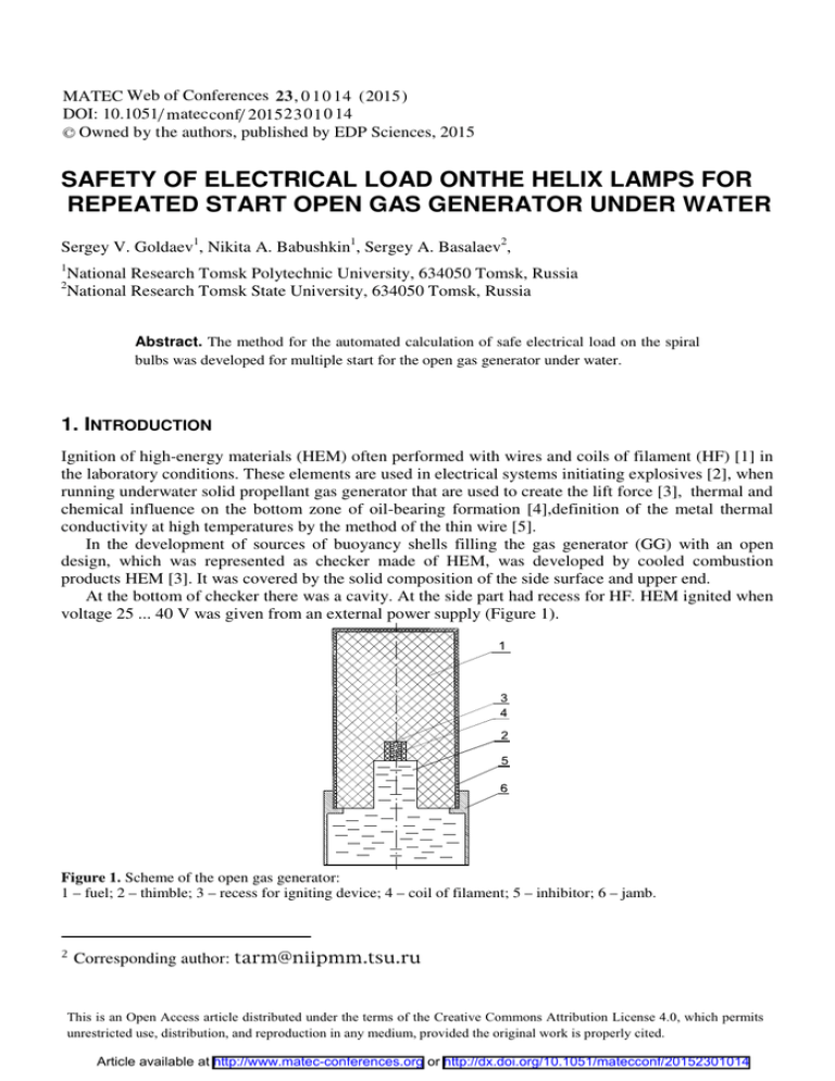
MATEC Web of Conferences 23 , 0 1 0 1 4 ( 2015) DOI: 10.1051/ m atec conf/ 2015 2 3 0 1 0 14 C Owned by the authors, published by EDP Sciences, 2015 SAFETY OF ELECTRICAL LOAD ONTHE HELIX LAMPS FOR REPEATED START OPEN GAS GENERATOR UNDER WATER Sergey V. Goldaev1, Nikita A. Babushkin1, Sergey A. Basalaev2, 1 2 National Research Tomsk Polytechnic University, 634050 Tomsk, Russia National Research Tomsk State University, 634050 Tomsk, Russia Abstract. The method for the automated calculation of safe electrical load on the spiral bulbs was developed for multiple start for the open gas generator under water. 1. INTRODUCTION Ignition of high-energy materials (HEM) often performed with wires and coils of filament (HF) [1] in the laboratory conditions. These elements are used in electrical systems initiating explosives [2], when running underwater solid propellant gas generator that are used to create the lift force [3], thermal and chemical influence on the bottom zone of oil-bearing formation [4],definition of the metal thermal conductivity at high temperatures by the method of the thin wire [5]. In the development of sources of buoyancy shells filling the gas generator (GG) with an open design, which was represented as checker made of HEM, was developed by cooled combustion products HEM [3]. It was covered by the solid composition of the side surface and upper end. At the bottom of checker there was a cavity. At the side part had recess for HF. HEM ignited when voltage 25 ... 40 V was given from an external power supply (Figure 1). Figure 1. Scheme of the open gas generator: 1 – fuel; 2 – thimble; 3 – recess for igniting device; 4 – coil of filament; 5 – inhibitor; 6 – jamb. Corresponding author: 7KLVLVDQ2SHQ$FFHVVDUWLFOHGLVWULEXWHGXQGHUWKHWHUPVRIWKH&UHDWLYH&RPPRQV$WWULEXWLRQ/LFHQVHZKLFKSHUPLWV XQUHVWULFWHGXVHGLVWULEXWLRQDQGUHSURGXFWLRQLQDQ\PHGLXPSURYLGHGWKHRULJLQDOZRUNLVSURSHUO\FLWHG Article available at http://www.matec-conferences.org or http://dx.doi.org/10.1051/matecconf/20152301014 MATEC Web of Conferences However, such GG can not be stopped in case of an emergency situation. To eliminate these, the method of burning underwater is provided [6], according to which 1 block is located in a liquid in a vertical position (Figure 2). Localization of the alleged burning zone at the upper end is achieved by using the heat-resistant glass (HRG) 2, at the bottom of which is located HF 3. HRG is set covering its sidewalls on the top of checkers, allowing the liquid to completely fill a gap formed between the walls and sword. Before the ignition bottom part HRG is heated to a temperature exceeding the ignition temperature Tcom, and then, the temperature is maintained during the combustion process. After HEM ignition on the upper end of the forced movement of the vehicle is carried out down, to stop the burning of the HRG either it is stopped or is diverted (Figure 2). Water 2 3 1 Water Combustion products 2 3 1 4 ɚ b Figure 2. Arrangement checkers and heat-resistant part in various stages of the ignition and combustion: ɚ) when the ignition; b) at spontaneous termination combustion. Stop or diversion HRG provides stopping of the burning process. At the top end of the checker 1 there is a stratum combustion products which are displacing residual liquid from the gap with free surface forming. 4. Then combustion products flow out and up. Experimental research of the method for VEM combusting in a liquid performed on samples made of HEM sticks type H of 20 mm diameter, set in upright position on a stand in a container filled with water [7]. At the upper end of checkers HRG was placed upside down in the bottom part of which HF was mounted. HRG was suspended on a block and could move freely in the vertical directions. The gap between the sample surface and the inner surface of the glass is (1 ... 2) mm and was filled with the liquid in the initial position. After applying a voltage, surface of the sample started heating and igniting. Current was (5 ... 6) A at 15 W power and the time of ignition was in the range (10 ... 20) seconds. After reaching steady state, HRG was pulled up and burning process stopped for a second. The test results showed that the method of HEM burning provides failsafe inflammation, reliable burning interruption. HF parameters [7] were chosen, and they were provided with the ignition checkers of used sizes. It remains an open question of permissible temperatures HF and places of its connection to connecting wires to ensure they remain in the closed state of the circuit for multiple HEM ignition when voltage is applied from the power source. While working time, [8] the ignition timing delay HEM ignition of the flat moderate power HF held by the simplified procedure, the temperature of which in the contact zone with the HF reaches Tcom § 500 K [1]. When you want to reduce the startup time open the generator, it is necessary to use powerful power supply or manufacture of CH thin and short wires. The temperature of the wire can reach 01014-p.2 TSOTR 2015 temperatures comparable to Tmel corresponding alloy with high specific resistance. Thermal properties of alloys with high electrical resistivity were presented in the Table 1 [9]. Table 1. Thermal properties of alloys with high electrical resistivity ȡh, Ɍmel, ɫ h, ȡ0Â108, Alloy 3 ɨ kg/m J/kg Ʉ OhmÂm °Ʉ ɋonstantan Nickel Nichrome 8900 8900 8400 410,33 468,84 460,57 49 7,24 110 1533 1426 1683 ȖÂ104, 1/°Ʉ (ȡh ɫh/ ȡ0) 1012 0,10 0,54 4,0 7,45 57,6 3,86 Key assumptions methodology. It is assumed that the wire is placed horizontally. It’s heated by the strength of current I, and it’s cooled by radiant and heat transferring convection in the free flow of air (tw = 0 °C) [5], [10]. Wire diameter dp, given the degree of blackness alloy İpr = 0,75; electric ( ) resistivity depends on the temperature ρ el = ρ 0 1 + γTs , where ȡ0 - electrical resistivity at 0 °C, Ȗ temperature coefficient of resistance of the alloy, 1/K, Ts - surface temperature of the wire. If the alloy has a temperature coefficient of resistance nichrome or less, its effect is not significant [11]. This effect will be amplified in the extended temperature range for HF. We will us the energy conservation equation and write the thermal balance for the portion of the HF. 2. METHODOLOGY The heat is released during the passage of an electric current through a conductor. It can be calculated by the formula Joule-Lenz. If HF cylindrical shape with a diameter dp and length lp, resistance Rel, then: 2 2 2 Q = I Rel = I ⋅ l p ⋅ 4 ȡ el /ʌ d p . What is the maximum current that can pass through the heater if the allowable temperature HF Tmel = 1683 ɨK? Cooling conductor at the expense of free convection and radiation to the environment. It has a temperature Tw, and can be recorded as [10]: [ )] 2 ­° ( 4 ȡ 0 1 + γ Ts − 273 I 2 ʌdp ½° ª§ Ts · 4 § Tw ·4 º = ®İ pr ⋅ c0 «¨ ¸ − ¨ ¸ » + Į k (Ts − Tw )¾ ʌ d p . °¿ °̄ ¬© 100 ¹ © 100 ¹ ¼ Here c0 - coefficient of blackbody radiation. We’ve got a non-linear equation with respect to the surface temperature of HF Ts. It was solved by the method of bisection. Interval finding solutions wondered physical considerations: Ts0 = 300 ɨK, Ts1 =4000 ɨK. Functions were calculated at these temperatures. The algorithm for calculating the desired temperature has been executed on a computer. The coefficient of heat transfer by free convection Įk was calculated by criterion equation [5], [10]. Nu m = Įk d p Ȝp Grashoff number for gases: 3 ( ( )n = C Gr ⋅ Pr m . )( 2 ) Gr = gd p Ts − Tw / Ȟ b Tm . 01014-p.3 MATEC Web of Conferences Here g - acceleration of gravity; Ȝb, Ȟb - coefficients of thermal conductivity and kinematic viscosity of air. Table 2. The values of the interpolation coefficients of criterion equation. <1,5·10-3 <5·102 Gr⋅ Pr ɋ 0,5 1,18 n 0 0,125 5·102…2·107 0,54 0,25 Calculation of the air thermal properties at different temperatures was carried out using interpolation formulas [12]: Proposition has been reduced to a nonlinear equation with respect to Ts. It was decided by the bisection. The coefficient of heat transfer by free convection Įk was calculated by criterion equation. Calculation of air thermal properties of at different temperatures was carried out with the help of interpolation formulas [12]: • dencity, kg/m3, ȡ b = ȡ 0 p / Tm , Here ȡ0 = 3,4839; p – dencity (kilopascal); • heat capacity, kJ/(kg.Kelvin), c pb = c1 + c2 t m , Here ɫ1 = 1,0005, ɫ2 = 1,1904 10 ; • coefficient of heat conductivity, W/(m. Kelvin), . -4 k Ȝ b = k 21Tm 22 , Here k21 = 0,37.10-3, k22 = 0,748; • coefficient of kinematic viscosity, m2/second, Ȟ b = 10 −4 (n21 + n22tm ) p0 / p , Here n21 = 13,7, n22 = 0,101, p0 = 98,07 kilopascal; • Prandtl number, Prb = Ȟ b ⋅ c pb ⋅ ȡ b /Ȝ b , 3. Results and discussion The calculation results: the temperature of the nichrome HF was Ts = 1341 ɨK, the following values of dp = 1  10-4 m, Lp = 0.015 m, the voltage of 3.5 V. the strength of the current 1,16 A. power HF 4.05 watts. Current up to 1.04 A. power HF to 3.13 watts, the temperature Ts to 1167 ɨK down when we reduced the voltage at 0.5 V. The HF length of 0.075 m and a diameter dp = 1  10-4 m at 16.5 V voltage has a temperature Ts =1275 ɨK. The current is 1.11 A, and the power of HF 18.33 watts. 4. Conclusion Thus, a method for the automated calculation of safe electrical load on the spiral bulbs for multiple launch an open gas generator under water worked out. This work was carried out with the financial support from the grant of the Russian Scientific Fond (project No. 15-19-10014). 01014-p.4 TSOTR 2015 References 1. V. E. Zarko, S. S. Khlevnoi. (1968) Ignition of a ballistite powder by heated wires. // Combustion, Explosion and Shock Waves 4: pp. 158-170. 2. M. M. Graevskii Handbook of electric blasting charge. Moscow, 1983 (In Russian). 3. V. D. Barsukov, S. V. Goldaev. Underwater ignition and combustion of unitary solid // Propellants. Theory, Experiment, and Technical Applications. Tomsk, 2003 (In Russian). 4. G. A. Chazov. Termogaz chemical effect on low-yield and complicated wells. Moscow, 1986 (In Russian). 5. A. S. Chernenko, V. V. Kalinchak, V. V. Kalugin. Determination of the thermal conductivity of metals at high temperatures by a thin wire // The Physics of Aerodisperse Systems. Vishcha Shkola, Kiev – 2012 – pp. 39–47. 6. V. D. Barsukov, S. V. Goldaev, N.P. Min'kov, and S.N. Polenchuk, “Method of unitary solid fuel combustion in liquid medium”. RU Patent No. 2345277. Publ. 27.01.209. Bull. No. 3. 7. V. D. Barsukov, S.V. Goldaev, N.P. Min'kova, S.N. Polenchuk. New way of underwater burning unitary solid fuel combustion front moving from top to bottom // The Fundamental and Applied Problems of the Mechanics- Tomsk: University Publishing House. – 2006 - pp. 64-65. (In Russian). 8. V. D. Barsukov, S.V. Goldaev, N.P. Min'kova, N.A. Babushkin. On ignition underwater dibasic solid fuel with a heat resistant glass filament helix average power // Power engineering: efficiency, reliability, safety. Scientific and Technical Conference – Tomsk, 2014 – pp. 163–166 (In Russian). 9. S.V. Goldaev. Thermal effects on condensed matter flat and cylindrical heaters – Tomsk, 2012 (In Russian). 10. S.V. Goldaev, Yu. A. Zagromov, Kovalev M. V. The solution of problems of thermal engineering environment Turbo Pascal. – Tomsk, 2006. (In Russian). 11. V. D. Barsukov, S.V. Goldaev, S. A. Basalaev. Calculation of the ignition of solid propellant spiral bulbs with the dependence of the electrical resistance of the temperature // Modern Technique and Technologies, International Scientific and Practical Conference of Students, Postgraduates and Young Scientists. MTT 2008. Tomsk. pp. 335–337 (In Russian). 12. P.I. Bajan, G.E. Kanevets, V.M. Seliverstov. Manual heat exchangers Moscow. 1989 (In Russian). 01014-p.5

