EE 215 Lab 2: Sinusoidal Steady State Power Measurement
advertisement
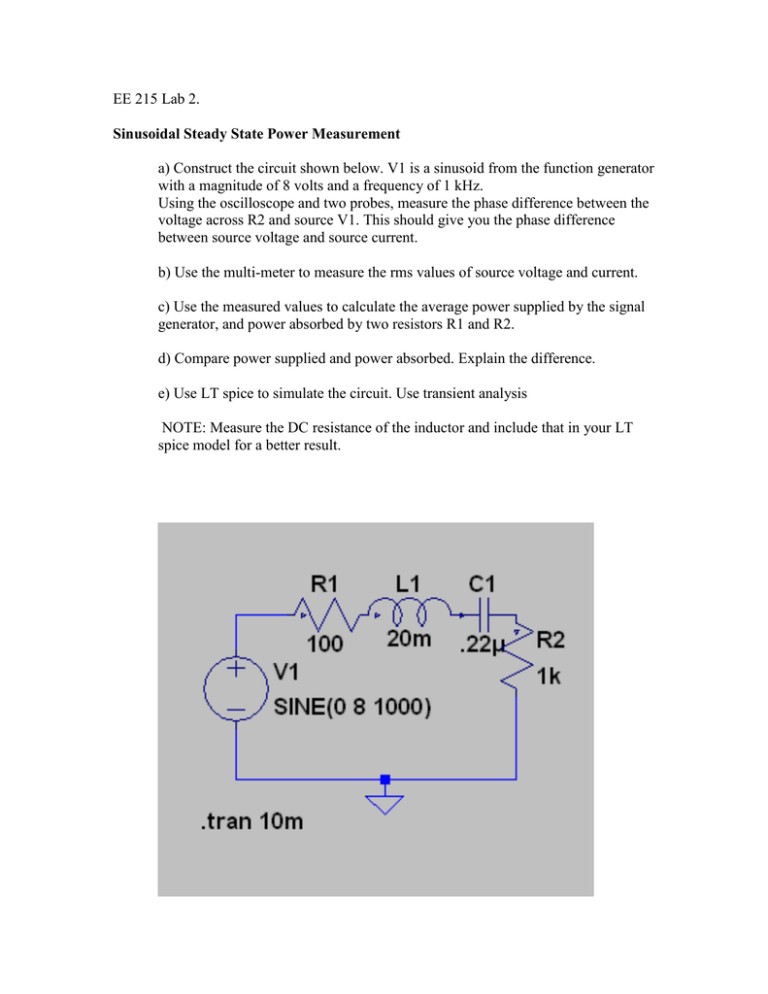
EE 215 Lab 2. Sinusoidal Steady State Power Measurement a) Construct the circuit shown below. V1 is a sinusoid from the function generator with a magnitude of 8 volts and a frequency of 1 kHz. Using the oscilloscope and two probes, measure the phase difference between the voltage across R2 and source V1. This should give you the phase difference between source voltage and source current. b) Use the multi-meter to measure the rms values of source voltage and current. c) Use the measured values to calculate the average power supplied by the signal generator, and power absorbed by two resistors R1 and R2. d) Compare power supplied and power absorbed. Explain the difference. e) Use LT spice to simulate the circuit. Use transient analysis NOTE: Measure the DC resistance of the inductor and include that in your LT spice model for a better result.

