From: AAAI Technical Report SS-92-01. Compilation copyright © 1992, AAAI (www.aaai.org). All rights reserved.
Scheduling Revisited
Integrated-Circuit
Workstations
Fabrication
in
Paul J. Kline
Semiconductor
Process and Design Center
Texas Instruments
Incorporated
P.O. Box 655012, M/S 3635
Dallas,
TX 75265
kline@csc.ti.com
Abstract
While good start plans have helped avoid someof the
problems of machine overloading and late orders, these
The cost of building new semiconductor wafer fabricaproblems have not totally disappeared in the wafer
tion factories has grown rapidly, and a state-of-the-art
labs. Machine breakdowns, rework, etc., make it inlab may cost $250 million or more. Obtaining an acevitable that production rarely proceeds as smoothly
ceptable return on this investment requires high proas desired. The manufacturing staff reacts to these
ductivity from the fabrication facilities.
disruptions by reprioritising lots of wafers to expedite
This paper describes the Photo Dispatcher system
lots that are behind schedule or to cure workload imwhich has been developed to make machine-loading
balances on equipment. We developed the Photo Disrecommendations at a sat of key fab machines. Dispatcher to investigate the possibility of automating the
patching policies that generally perform well in job
scheduling of a sat of key machinesin the photolithogshops (e.g., Shortest Remaining Processing Time) perraphy area.
form poorly for workstations such as photolithography
The photolithography area was chosen because lots
which are visited multiple times by the same lot of
continually revisit this area during their processing,
silicon wafers.
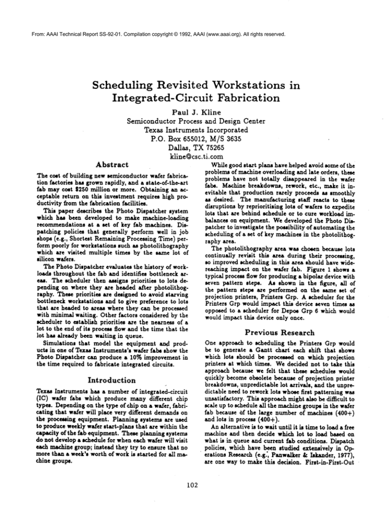
so improved ~heduling in this area should have wideThe Photo Dispatcher evaluates the history of workreaching impact on the wafer lab. Figure 1 shows a
loads throughout the fab and identifies bottleneck artypical process flow for producing a bipolar device with
eas. The scheduler then assigns priorities to lots deseven pattern steps. As shown in the figure, all of
pending on where they are headed after photolithogthe pattern steps are performed on the same sat of
raphy. These priorities are designed to avoid starving
projection printers, Printers Grp. A v.heduler for the
bottleneck workstations and to give preference to lots
Printers Grp would impact this device seven times as
that are headed to areas where they can be processed
opposed to a scheduler for Depos Grp 6 which would
with minimal waiting. Other factors considered by the
would impact this device only once.
lw.heduler to establish priorities axe the nearness of a
lot to the end of its process flow and the time that the
Previous
Research
lot has already been waiting in queue.
Simulations that model the equipment a~l prodOne approach to scheduling the Printers Grp would
be to generate a Gantt chart ~ each shift that shows
ucts in one of Texas Instruments’s wafer labs show the
which lots should be processed on which projection
Photo Dispatcher can produce a 10% improvement in
printers at which times. Wedecided not to take this
the time required to fabricate integrated circuits.
approach because we felt that these schedules would
quickly becomeobsolete because of projection printer
Introduction
breakdowns, unpredictable lot arrivals, and the unpreTexas Instruments has a number of integrated-circuit
dictable need to rework lots whosefirst patterning was
(IC) wafer labs which produce many different chip
unsatisfactory. This approach might also be difficult to
types. Dependingon the type ofchip on a wafer, fabriscale up to schedule all the machinegroups in the wafer
cating that wafer will place very different demandson
lab because of the large number of machines (400+)
the processing equipment. Planning systems are used
and lots in process (400+).
to produce weekly wafer start-plans that are within the
Analternative is to wait until it is time to load a free
capacity of the lab equipment. These planning systems
ma~ine and then decide which lot to load based on
do not develop a schedule for wheneach wafer will visit
what is in queue and current fab conditions. Dispatch
each machine group; instead they try to ensure that no
policies, which have been studied extensively in Opmore than a week’s worth of work is started for all maerations Research (e.g’, Panwalker & Iskander, 1977),
chine groups.
are one way to make this decision. First-in-First-Out
i02
Process
Step
Step Type
Equipment
First Oxidation
DUF Pattern
DUF Diffusion
Epitaxial
Deposition
Second Oxidation
Isolation
Pattern
Isolation
Diffusion
Base Pattern
Base Diffusion
EmitterPattern
Emitter Diffusion
Contact Pattern
Aluminum Evaporation
Metal Pattern
Deposit Overcoat
Bonding Pad Pattern
ElectricalTest
Layer
Pattern
Dope
Layer
Layer
Pattern
Dope
Pattern
Dope
Pattern
Dope
Pattern
Layer
Pattern
Layer
Pattern
Test
FurnaceGrp I0
PrintersGrp
FurnaceGrp 20
Epi Reactors
FurnaceGrp I0
Priatore
Grp
Furnace Grp 32
PrintersGrp
Furnace Grp 83
Printers
Grp
Furnace Grp 60
Printers
Grp
£1ua Evap Grp
Printers
Grp
Depo8 Grp 6
PrintersGrp
Tester Grp
Figure 1: All of the pattern steps are
photolithography area of the lab on
ment, Printers Grp. Wafers fabricated
ce~ flow illustrated makeseven visits
theirduedates.Whatcausesproblems
is that"winner
takeall"schemes
basedon thesefactors
runtherisk
thatlowpriority
lotsmaywaitforever
ifhigher
priority
lotsarrivefastenough.
To getaroundthisproblem,
thePhotoDispatcher
usesa variation
of a round-robin
schemewhichprovides
a "winner
takea biggershare"
selection.
TheFIFOdispatch
policyis notbiasedin favorof
particular
pattern
steps,
butit is myopic
inthesense
thatitwillselect
lotsthatwilljusthavetositattheir
nextprocess
stepbecause
a keymachine
is down.Alternatively,
itmaypassoverlotsthatwouldhelpkeepa
downstream
bottleneck
machinegroupfromstarving.
Goldratt’s
OPT system(1984,1988)emphasised
the
importance
of bottleneck
resources
in scheduling.
AI
scheduling
systemsthatemphasize
theimportance
of
bottleneck
resources
includeSmith,Fox,& Ow (1986)
and Eskey& Zweben(1990).The PhotoDispatcher
avoidsmyopicdecision
makingby monitoring
current
andhistorical
workloads
throughout
thewaferlaband
reacting
to theseworkloads
to avoidstarving
bottleneckworkstations
andavoidsending
lotsto workstbtionswheretheywilljustsitin queue.
performed in the
the same equipusing the proto Printers Grp.
Approach
The PhotoDispatcher
makesrecommendations
about
whichlotof wafersin thequeueshouldbe processed
nextby Printers
Grp.ThePhotoDispatcher
develops
theserecommendations
in threestages:
(FIFO) is an example of a simple dispatch policy.
However,for the current application, dispatch policies have the following drawbacks:
1.Establish
priorities
forprocessing
lotsatthedifferentpattern
steps.
2. Usethepriorities
to choose
a pattern
stepto workon
next.Thatis,decidewhether
to workon a lotthat
is waiting
forDUFPattern,
or Isolation
Pattern,
etc.
I. Manydispatch policies do not work well on revisited
machine groups like Printers Grp.
2. The typical dispatch policy is myopic in the sense
that it considers only the local situation and does not
consider the needs of downstream machine groups.
A dispatch policy such as Shortest Remaining Pro.
ce~ Time (SRPT) will lea~i to problems when applied
to a revisited workstation like the Printers Grp. If the
queue for Printers Grp is ma~te up of a number of lots
with the process flow shown in Figure 1, then SRPT
will prefer lots that are at their last pattern step, Bonding Pad Pattern. It will only select lots at the first
p6ttern step, DUFPattern, if there are no other lots
in the queue. This leads to long waiting times at DUF
Pattern and alternating starve/glut feeding patterns
for DUFDi~usion.
Wehave investigated other dispatch policies such as
Shortest Processing Time and Slack to Due-Date, but
our experience has been that they also share the defect
of SRPTof being biased in favor of one or another of
the pattern steps and neglecting others. The problem
seem- to be that these policies are "winner take all"
policies ms opposed to "winner take a bigger share"
policies. There is nothing wrong with adding priority
to lots near the end of their flows or lots in trouble with
lotwaiting
forthatpattern
step.
3. Choosea specific
Therearetypically
several
lotswaiting
forDUFPatternandthisthirdstagedetermines
whichof these
lots shouldbe recommended.
Whilea numberof
different
criteria
havebeeninvestigated
formaking
thislotselection,
noneof themhaveoutperformed
FIFO,so currently
thisselection
is justbasedon
timeof arrival
ofthelots.waiting
forDUFPattern.
103
Pattern-Step
Priorities
Figure 2 gives an exampleof the calculation of priorities for four pattern steps. Three numbers are summed
to determine priorities. The percentage of lots waiting
for a particular pattern step (e.g., 20 percent for DUF
Pattern) is added to a number that is based on the
nearness of that pattern step to the end of the pro.
cessing flow (e.g., 01, the first two digits of the step id
number). Finally, a positive number(e.g., 30) is added
if more work is needed at downstream work areas or
a negative number is added if there is too muchwork.
The higher the priority number for a pattern step the
more lots at this step will be recommendedfor pro-
ceasing. The rationale for each of the three factors
illustrated in Figure 2 will be discussed in turn.
% Lots Queued If the process flow in Figure 1 was
used by all devices, there would be roughly equal numbers of lots waiting for the individual pattern steps.
However,since there are roughly 300 different process
flows, the pattern steps do not occur with equal frequency. Including a factor for the percentage of lots
waiting for a particular pattern step ensures that the
round-robin sr.)~eme does not penallse lots that are
waiting for frequently used pattern steps.
0100 DUFPATTERN
Lots O~*ued 20
Flow Position
O1
Feedback
30 (Send More;
Shor~ Wait at
Furnace Grp 20)
Priority
Sl
Flow Position The second factor,
nearne~ of a
pattern step to the end of the process flow, has the
effect of reducing work-in-process (W’IP). Lou and
Kager (1989) recommend that when scheduling revisited workstations in IC fabrication, higher priority
should be given to process steps that are later in the
proce~ flow. Our experiments confirm the benefits of
this practice.
0600 ISOLITZONPATTE~I
Lots Queued
04
06
now Position
Feedback
-30 (Send Less;
....
Long Wait at
Priority
-20 Furnace Grp 32)
2300 BASE PATTERN
Lots Oueued 12
Flog PositLon
23
Feedback
00 (No £djustmenZ;
Average Wait at
Furnace Grp 53)
Priority
3S
6000 COITACTPATTERN
Lots Queued
Flog Position
Feedback
08
60
60
Priority
125
(Send Much More;
Starving Bottleneck
Alum Evap Grp)
Figure 2: Three factors determine the priority of a particular pattern step: the fraction of lots waiting for this
pattern step, the nearness of this pattern step to the
end of the process flow, and feedback from downstream
work areas.
Feedback
From Downstream
Workstations
The feedback to Contact Pattern in Figure 2 shows
a bottleneck, AlumEva/) Grp, requesting additional
work because it is starving. Figure 3 illustrates the
computations performed to determine this machine
group is a starving bottleneck. A software object called
a Work Monito~ is associated with mar.bins ~oups in
the lab. WORK-FOR-ALUM-EVAP
knows how to use
¯ the current po4ition of a lot provided by the WIPtracking system to determine whether that lot is at a process
step that uses the AluminumEvaporators. In the case
illustrated in Figure 3, there is one lot consisting of
48 wafers arrived at a processing step using the Aluminum Evaporators.
WOR.K-FOR-ALUM-EVAP
can tel] if a lot has left photolithography and is on the
way to a process step using the AluminumEvapora.
tors but has not arrived yet. Identifying lots that have
been sent to the AlumEvap Grp provides an estimate
of upcoming wor]doack.
WORK-FOR-ALUM-EVAP
knows how to translate
the number of wafers arrived into the time it should
take the AlumEvap Grp to complete processing those
wafers. In Figure 3 the 48 wafers arrived are estimated
to keep the AluminumEvaporators busy for the next
.58 hrs. The following factors are considered to determine how many hours it will take to complete proceuing a particular set of wafers:
1. number of machines in Alum Evap Grp and their
capacities
2. process time for ear.h wafer; different devices may
have different processing times
3. setup times
Work Monitors categorise worklo~is along four
different
dimensions (TYPICAL-LOAD, COMPARENOW-TO-HISTORY,
etc.) and these dimensions are
referenced by rules that determine the appropriate
104
feedback (e.g., send MUCH
MORE).By changing the
feedback rules, a wide w.riety of workloszi regulation
schemes can be implemented. Simulation experiments
were run to evaluate three different workload regulation schemes: Bottleneck Starvation Avoidance, Small.
est Next Queue, and Workload Smoothing. Each of
these three workload regulation schemes performed
well at some WIPlevels, but none of the three was superior at all WIPlevels. A hybrid of these approaches
was devised which performed well at all WIP levels
investigated.
Some approaches to scheduling using bottleneck
starvation avoidance require that the there is only one
bottleneck and its identity is known in advance and
provided as input to the scheduler (e.g., GlaJmey&Resende 1988). This a~umption makes it di~cult to handle shifting bottlenecks which can arise in wafer fabs
because of a change in product mix or the breakdown
of key equipment. The work-moultoring mechanism of
the Photo Dispatcher determines which workstations
are bottlenecks by gathering workload histories. As
the bottlenecks change over time the shift in workload
histories is tracked by the WorkMonitors and the priority of lots is changedaccordingly.
VORK-FOR-ALUM-EVAP
Lots sent to Alum Evap Grp: 0 lots, 0 wafers
Lots arrived at Alum Evap Grp:
1 lot, 48 wafers
Eat work in queue for Alum Evap Grp:
14 wafers,0.26 hrs
Eat work in processfor Alum Evap Grp:
34 wafers00.32 Ere
Estimatedwork available: .88 hrs
The avg amount of work, 10.43 Era, that
arrivesin this area is HIGH relativeto the
long-runavg (4.44 hrs, sigma=3.19)
for all areas.
Work currently
arrived in this area, .58 hrs,
is LOWrelative
to the long-run avg
(10.43 hrs, |i~a-6.28)
for this area.
Work currently
arrived in this area, .$8 hrs,
is LOWrelative
to the avg currently
arrived
(3.61 hrs, sipa:3.66)for all areas.
Work currentlysent to this area, 0.00 hrs,
is LOW relative
to the long-run avg
(2.70 hrs, sigma:O.64)for this area.
Using Priorities
to Select a Pattern Step
Priorities are recomputed periodically based on the
current workloads at downstream machine groups and
the number of lots queued for each pattern step.
The priorities influence subsequent selection of pattern
steps by controlling a round-robin scheme.
Each time a ~e in Printers Grp is ready to be
loaded, the round-robin advances to the next pattern
step in the cycle. The priority assigned to this pattern step determines whether a lot is chc4en from this
pattern step or whether the round-robin immediately
advances to the next pattern step. Priority numbers
are rescued to range from 5 to I00 and pattern steps
with priority 5 have a lot selected one out of every 20
times the round-robin stops there (5%), pattern steps
with priority 50 have a lot selected every other time
the round-robin stops there, etc.
Whenthe priorities
are as shown in Figure 2, a
sequence of selections produced by this round-robin
might be Contact Pattern, DUFPattern, Base Pattern, Contact Pattern, Contact Pattern, DUFPattern,
Contact Pattern ..... By interleaving pattern steps in
this fashion there is limit on how many times a low
priority pattern step can be passed over before it is
selected.
The classification
is:
TYPICAL-LOAD
HIGH
COMPi~E-|OW-TO-HISTORYLOW
COMPARE-TO-OTHER-MACHS
LOW
COMPAI~E-SENT-TO-HISTOR¥
LOW,
so MUCHMOREwork is needed.
Figure 3: An example of a starving bottleneck. The
Aluminum Evaporators typically
have 10.43 hrs of
work; however, at the time this workload evaluation
was performed there was only .58 hrs of work and none
on the way. A request for much more work is fed back
to Contact Pattern.
Results
The Photo Dispatcher was tested using a simulation
of one of Texas Instruments’ wafer labs. The lab in
question manufactures a wide variety of Bipolar and
BiMOSdevices. The simulation modeled all of the 103
machine groups (410 nmehmes)
~n the lab and all of the
process steps needed to fabric6te any of the roughly
105
INITIAL
WIP
290
400
675
1000
FIFO
CT
Output
339
140
482
132
680
138
1068
132
Photo Dispatcher
CT
Output
328
140
427
136
604
141
975
136
ingof fab operation,.
However,
itsWorkMonitor
pability
hu beenusedto a limited
degreeto analyse
production
problems
in labs.
Table 1: In simulation experiments, the Photo Disl~tcher produces an improvement over a FIFO policy
in the averse number of hours needed to complete
proce~ing a lot of wafers (i.e., cycle time or CT). The
same lot starts were used in all simulations, so WIP
levels were manipulated by varying the number of initial WIPlot, in the fab at the start of simulation.
300 different ICs produced. There are roughly 50 procuss steps in the recipe for a typical IC in this lab and
these process steps are broken downin the simulation
to 165 separate operations ea~ of which requires the
use of another machine. The simulation included randomntachine breakdowns, but this was the only random component as proce~ming times were mumeddeterministic, lot transport time was not modelled, and
there were no operator limitations.
Table I shows the Photo Dispatcher ha, better averqe cycle-time performance in simulations than ¯ FIFO
policy. FIFO does not separate the decision of which
lot to proceu next on Printers Grp into a pattern step
selection followed by a lot selection. Instegd it merely
finds the lot that has been waiting longest for the printera and starts that lot. This is the default behavior of
the simulator and it is alto used when exercising the
Photo Dispatcher for machine groups other than the
Printers Grp.
The sise of the cycle-time improvement depends on
the amount of WIPin the simulated lab. At WIPlevels
above 400 lots, the Photo Dispatcher reduced cycletimes by roughly 10% with greater output in terms
of finished lots per week. Since the fab being simu.
fated currently operates at WIPlevels in exce~ of 400
lots, a 10%cycle-time improvementwas projected from
the nse of this scheduler. Results to date suggest that
flow polition is the most important factor in producing
cycle-time improvements of the three factors combined
in Figure 2.
Summary
The Photo Dispatcher provides an e~ective echedulhag approach for revisited workstations such a8 photolithography in IC fabrication. It takes advantage of
the unique opportunity that these revisited workstation- provide to shift workloads from one downstream
area to another and to reduce WIP by speeding up
process/a s on lots near the end of their process flows.
While the Photo Disptacher was developed with the
intention of installing it in Texas Instruments’ wafer
labs, to date it has not been used for real-time schedul106
References
Eskey,M. andZweben,
M. Learning
searchcontrolfor
constraint-betsed
scheduling.
ProceedingmEighth
~LVational Conference
on Artificial Intelligence (AAAI.90),
1990, pp. 908-915.
Glassey, C.R. and Resende, M.G. Closed-loop job
release control for VLSIcircuit manufacturing. /’EEE
~eanaactionJ on Semiconductor Jilanu/acturing, Vol.
1, 1988,
Goldratt, E. and Cox, J. The Goal. North River
Press, 1984.
Goldratt, E.M. Computerised shop floor scheduling
Intery, ational 3o,~,r, al o/ProductionResearch.Vol.26,
1988, pp. 443-455.
Lou, S.X.C. and Kager, P.W. A robust production
control policy for VLSIwafer fabrication. IEEB2~anaactions on Semiconductor Manu/actueing, Vol. 2, No.
4, 1989.
Panwalker, S.S. and hk*nder, W. A survey of
scheduling rules. Ope~tiona ReseaT’oh, Vol. 25, 1977,
pp. 45-61.
Smith,S.F.,Fox,M.S.,and Ow,P.S.Constructing
andmaintaining
detailed
production
plans:Investigationsintothedevelopment
of knowledge-based
factory
scheduling
systems.
A]"Ma0~ine,
Fail1986,pp. 4561.

