AAA11994Spring Symposiumon Medical Applications of Computer Vision
From: AAAI Technical Report SS-94-05. Compilation copyright © 1994, AAAI (www.aaai.org). All rights reserved.
Shape-Based Grayseale Interslice
Image Interpolation
William Barrett and Eric Bess
Department of Computer Science, Brigham Young University
Provo, UT 84602, barrett@cs.byu.edu
Abstract
(x,y)
A new algorithm for interpolation between
grayscale serial slice images, such as from CT, is
presented. The algorithm extends shape-based
(SB) binary image interpolation to shape-based
interpolation of grayscale images (SBIG). Unlike
algorithms, such as linear (L) or cubic spline (CS)
interpolation, whichrely only on pixel position,
SBIGmakesessential use of object distance and
morphology to interpolate between pixels and
structures of similar shape and intensity whichmay
differ in size and position from slice to slice. For
reasonably low noise MR/, CT, and Cine CT grayscale images, results are superior visually and
quantitatively (15%)to interpolation based solely
on (x,y) proximity, particularly as the interslice
spacing is increased. Moreimportantly, while both
L and CSinterpolation demonstrate characteristic
low-passsmearingof object edges and detail, these
features are preserved and well approximatedwith
SBIG. As a result, reconstructed coronal and
sagittal slices from a densely interpolated image
volume using SBIG demonstrate significantly
clearer representation of anatomicalstructures and
less "staircasing" than those created using either L
or CSinterpolation. Clipping artifacts due to
nonoverlapping structures or rapid changes in
image brightness are minimized using simulated
three-dimensional distance maps.
Introduction
Acquisition of serial cross-sectional slice
images has becomeubiquitous in medical imaging.
Becauseinterslice spacingis typically greater than
intraslice spacing, imageinterpolation techniques
often are used to fill in the interslice spaces and
produce a uniformly dense image volume.
Avariety of linear, trilinear, and spline-based
image interpolation techniques1-3 have been used
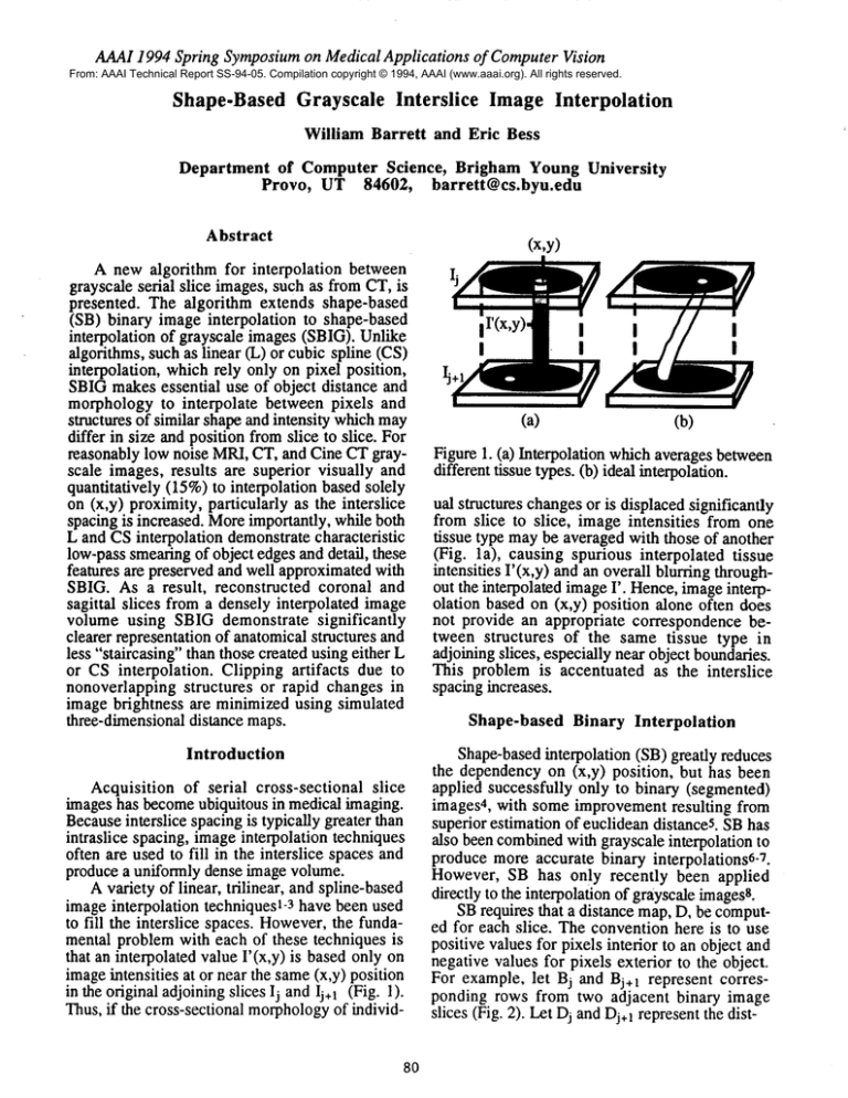
to fill the interslice spaces. However,the fundamental problem with each of these techniques is
that an interpolated value I’(x,y) is based only
imageintensities at or near the same(x,y) position
in the original adjoiningslices lj and lj+ 1 (Fig. 1).
Thus, if the cross-sectional morphology
of individ-
80
I
I
I
(a)
I
I
I
I
(b)
Figure 1. (a) Interpolation which averages between
different tissue types. (b) ideal interpolation.
ual structures changesor is displaced significantly
from slice to slice, image intensities from one
tissue type maybe averaged with those of another
(Fig. la), causing spurious interpolated tissue
intensities I’(x,y) and an overall blurring throughout the interpolated imageI’. Hence,imageinterpolation based on (x,y) position alone often does
not provide an appropriate correspondence between structures of the same tissue type in
adjoining slices, especially near object boundaries.
This problem is accentuated as the interslice
spacing increases.
Shape-based Binary Interpolation
Shape-basedinterpolation (SB) greatly reduces
the dependency on (x,y) position, but has been
applied successfully only to binary (segmented)
images4, with some improvement resulting from
superior estimation of euclidean distanceS. SBhas
also been combinedwith grayscale interpolation to
produce more accurate binary interpolations6-7.
However, SB has only recently been applied
directly to the interpolation of grayscale imagesS.
SBrequires that a distance map,D, be computed for each slice. The convention here is to use
positive values for pixels interior to an object and
negative values for pixels exterior to the object.
For example, let Bj and Bj+I represent corresponding rows from two adjacent binary image
slices (Fig. 2). Let Dj and Dj+]represent the dist-
AAA11994Spring Symposiumon Medical Applications of ComputerVision
~)j+1
12 34 4 3 21
..
3j+ 111111111111111
imlmmml
X
:igum 2. Shape-basedbinary interpolation.
Results
race mapsfor Bj and B j+l. The interpolated bitary slice, B’, is obtained by thresholding (’dO)
he weighted average of Dj and Dj+I. For
.xample,B’(x=6) = 1 since .5[Dj(6)+Dj+I(6)]
5[-1 + 4] -- 1.5 > 0, assumingB’ is midway(.5)
~etween Bj and Bj+I.
;hape-based Grayseale Interpolation
TheSBalgorithm is applied to interpolation of
;rayscale images by treating them as n binary
rnages, Bk(X,y),k =l...n wheren is the bit-depth
~solution of the original grayscale imagesIj and
,+1. Specifically, the interpolated image
I’(x,y) = max[B’k(x,y)], for k = 1 to n.
’or example,if Ij is an 8-bit image,then n = 255.
f each Bk is defined by a thresholding operation
n the original image,such that
Bk(X,y)=
=
k for Ij(x,y)> k
0, otherwise
[2]
mnIi can be exactly representedas
Ij(x,y)
=max[Bkj(x,y)].
[3]
k
hus, an interpolated grayscale image slice, r,
etween two adjoining images Ij and Ij+l can be
btained by first applying equation [2] to Ij and
+1 separately to produce corresponding binary
nages Bk,j and Bk,i+t, for each k =l...n, and then
?plying the SB binary algorithm to obtain an
tterpolated binary image B’k, for each (Bk,j,
k,j+t), k =l...n.
B’k=SB(Bkj,Bkj+l)
obtained
by maximizing
overallB’k,as shown
in
equation
[I].
Oneof theproblems
withSBIGis thatif an
object
ispresent
inoneoftheoriginal
slices,
but
absentin thenext,theobjectmay be clipped
abruptly.
However,
thiscanbe partially
overcome
by combining
2D distance
mapsfromtheoriginal
slices,
Ij andIj+l,witha simulated
3D distance
mapin orderto linearly
extrapolate
theclipped
structure
fromoneslice
tothenext(SBIG+).
[4]
he final interpolated grayscale image, I’, is then
81
The complexity of the SBIG algorithm is
O(Ng) time and O(Ng) memory, where
numberof pixels in the image and g = numberof
gray levels. The SBIGalgorithm has been implemented on an HP 700 workstation. Computetimes
for a 2562x 8 image are 2.1, 4.3, and 430
seconds for L, CS, and SBIGrespectively.
Visual Comparison
Comparisonof SBIGwith linear CL) and cubic
spline (CS) interpolation, is performedby excluding an imageslice, Ij, froma set of serial slices and
then attempting to recreate Ij by interpolating
betweenIj’s neighboringslices, Ij.1 and Ij+l. Let
IL, Ic, and Is represent Ij recreated using L, CS,
and SBIG, respectively. This type of comparison
is first applied to two of eight 8mmthick Cine CT
scans through the opacified left ventricle at end
diastole. Figures 3a-c show the original third
(Ij_l=I3), fourth (Ij=I4), and fifth (Ij+1=I5)slices.
Slices I3 and I5 are separated by a 12mmgap. The
objective is to recreate 14 by interpolation. I4 is
recreated in figures 3d-f by applying L, CS, and
SBIGinterpolation respectively to slices 13 and I5.
Note that the SBIGalgorithm preserves high
frequency imagefeatures such as left ventricular,
myocardial, and lung boundaries. Also, the
structure of the left ventricle is reasonably well
approximated by SBIG, whereas L and CS
interpolation introduce low frequency information
and intermediatepixel intensities (not present in 13
and 15) by averaging pixel intensities
from
differing tissue types. This is particularly
noticeable along the myocardial-lung and left
ventricular-myocardial boundaries.
SBIGwas applied to the entire cardiac Cine CT
imageset, resulting in 103 total (8 original + 95
interpolated) slices from which reconstructed
coronal slices were extracted (Figure 4a). The
samereconstructed coronal slice obtained from L
and CS are shown in figures 4b and 4c. The
AAAI 1994 Spring Symposiumon Medical Applications of ComputerVision
smearing effect found in the L and CS crossand the preservation of sharp, distinguishable
sectional slices is even more pronouncedin the
anatomical structures and boundaries. SBIGis
coronal view, while the coronal view producedby
more of a content based interpolation technique
than L or CSin that it attempts to preserve similarSBIG demonstrates well-defined anatomical
regions from the original data slices that have
boundaries and overall smootherrepresentation of
object structure.
changed in size, position or shape. SBIG is
Sagittal views were also reconstructed from a
usually fairly successful in handlingthese changes,
CT data set of the head containing 64 original
especially for larger regions and wherethe regions
abutting scans, 1.5mmthick. Comparisons were
overlap. It is less successful at preserving small,
performedusing only 15 of the original 64 slices.
rapidly changing regions. A summaryof features
A mid-sagittal view comprised of all 64 slices
andliabilities follows.
(linearly interpolated = gold standard) is shown
figure 5a. Correspondingsagittal views for SBIG Features of SBIG:
L, and CS, (shown in figures 5b-d) consist of
¯ Doesnot introduce artificial imageintensities
total of 226 (210 interpolated) slices. Notethat the
¯ Omission of low frequency blurring
smearing artifacts associated with L and CS are
¯ Preservation of sharp anatomical boundaries.
still present, while object boundariessuch as skull
¯ Visual and quantitative improvementfor
and skin are more faithfully represented with
low noise images.
SBIG. SBIGalso avoids "ghosts" (i.e. artificial
¯ Possibility of requiring feweroriginal slices.
intermediate pixel intensities whichoccur in L or
CS(Fig. 6). However,figure 5b does demonstrate
Liabilities:
some of the limitations of SBIG. Namely, if
¯ Computationally more expensive.
objects fail to overlap from slice to slice, pixel
¯ Contouring and "patchy" appearance in noisy
intensities produced by SBIGwill diminish, as
areas.
demonstratedby the soft vertical banding in the
¯ Loss of structure in nonoverlappingregions.
skull. Also, if an object is present in one of the
¯ Objectclipping if the object only appears in one
original slices, but absent in the next, the object
original slice
maybe clipped abruptly. This can be seen when
comparing Fig. 5b with 5a and 7b with 7a where References
clipping is perceived as a diminishedintensity in
1. S. Raya,J. Udupa, and W.Barrett: "A PC-Based3D
the bony anatomy. However, this is overcome
ImagingSystem:Algorithms,Soft-ware,and Hardware
using a simulated 3D distance map(SBIG+, Fig.
Considerations." J. of Comp.Med. Imagingand
7c).
Graphics,Vol. 14, Number
5, :353-370,March,1990.
2. C. Upsonand M.Keeler, "V-Buffer:Visible Volume
Quantitative Comparison
Rendering,"Computer
Graphics22 (4) :59-64, 1988.
Quantitative comparison of L, CS, and SBIG 3. R. Burden
and J. Faires, Numerical
Analysis.Prindle,
is obtained by computingerror measuresEL=IIj-ILI,
Weber&Schmidt,BostonMA,1985.
EcIIj-lc I and Es=lIj-Isl as a function of the number 4. S. Rayaand J. Udupa,"Shape-based
Inlerpolationof
of slices skipped. The average error for Es is
Multidimensional
Objects," IEEETrans. on Medical
consistently lower than that for ELand Ec by about
Imaging,9(1) :32-42,1990.
three gray levels per pixel, or about 15%less
5. G. Herman,"Shape-basedInterpolation," Computer
Graphics
andApplications,Vol.12, (3) :69-79,1992.
overall. In general, except for very closely spaced
6. R. Lotufo, G. Herman,and J. Udupa,"Combining
Ij-1 and Ij+l, results showEs < EL, Ec, especially
Shape-basedand Gray-level Interpolations," Vis.
as the distance betweenIj-1 and Ij+ 1 increases.
BiomedComput.SPIEVol. 1808,:289-298,1992.
W.Higgins,et al., "Shape-Based
Interpolationof Tree7.
Conclusion
LikeStructures in Three-Dimensional
Images,"IEEE
Trans
Med
Imag,
V.
12,
No.
3,
:439-450,
Sept. 1993.
SBIGhas been applied successfully to CT,
8.
R.
Stringhum
and
W.
Barrett,
"Shape-Based
InterpolaCine CT, and MRIgrayscale images. For reasonation
of
Grayscale
Serial
Slice
Images,"
SPIE
Medical
bly low noise images, results are superior visually
Imaging:
Vol.
1898
Image
Processing,
:105-115,
1993.
and quantitatively to interpolation based solely on
(x,y) proximity. This is particularly true as the
interslice spacing increases. Of greatest significance is the omission of low frequency blurting
and artificial intensities associated with L and CS
82
AAA11994Spring Symposiumon Medical Applications of Computer Vision
@
(a)
(b)
(e)
(d)
Ce)
(0
Fig.
3 (a-c)
Original
slices
3,4,and5 t~"ough
theleft
ventricle.
(d-f)
Reconstruction
ofslice
4 (b)using
Fig.4 Coronal
viev(103slices,
0 original)
linear
interpola~on
(e)cubic
splJns
interpoktion
and
using
Ca)SBIO
(b)linear
(e)cubic
(I)SBIG.
Ca)
(b)
(c)
(d)
Fig. 5 lqid-s~gittal reconstructionusing (a) 64 or~h~lslices, 162linearly inlerpolaled, 226total.
(b-d)
15of64original
slices,
211in~rpolated,
226total
usL~(b)SBIG(c)linear(d)
cubic
Fig.
6 (a) ori.gineO.
(b) SBIOinterpolated
(c)Cubic
Spline
interpola~on
creates
artificiel intermediate
intensi~s
("ghosts")
atair-~sue
interface.
83
Fig.
7Ca)ox~ina]
(b)SBIGinterpolated
(c)SBIG+inlerpolated
boosts
intensities
vhichothervise
get
clipped
in SBIG.

