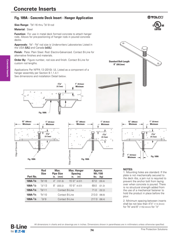
Fig. 109A - Concrete Deck Insert - Hanger Application
advertisement

Concrete Inserts Fig. 109A - Concrete Deck Insert - Hanger Application Size Range: 3/8"-16 thru 7/8"-9 rod Material: Steel Function: For use in metal deck formed concrete to attach hanger rods. Allows for pre-positioning of hanger rods in poured concrete decks. Approvals: 3/8" - 5/8" rod size is Underwriters Laboratories Listed in the USA (UL) and Canada (cUL). Finish: Plate: Plain Steel. Rod: Electro-Galvanized. Contact B-Line for alternative finishes and materials. Standard Bolt Length 8” (203.2mm) Applications Per NFPA 13 (2010): UL Listed as a component of a hanger assembly per Section 9.1.1.4.1 See dimensions and installation Detail below. 11/4” (31.7mm) 1” (25.4mm) Minimum 1î A Fig. 109A 12” (305mm) Minimum 12” (305mm) Minimum 1” (25.4mm) Minimum Edge of Concrete Edge of Concrete Part No. Max. Pipe Size in. (mm) Fig. 109A Max. Hanger Spacing in. (m) Approx. Wt./100 lbs. (kg) 109A-3/8 3/8"-16 4" (101.6) 15’-0” (4.57) 67.0 (30.4) 109A-1/2 1/2"-13 8" (203.2) 15’-0” (4.57) 69.0 (31.3) 109A-5/8 5/8"-11 Contact B-Line 71.0 109A-3/4 3/4"-10 Contact B-Line 213.0 (96.6) 109A-7/8 7/8"-9 Contact B-Line 217.0 (98.4) (32.2) 1” (25.4mm) Minimum 11/4” (31.7mm) 11/4” (31.7mm) Fig. 109A Rod Size 12” (305mm) Minimum 1” (25.4mm) Minimum 11/4” (31.7mm) Edge of Concrete Concrete Inserts Order By: Figure number, rod size and finish. Contact B-Line for custom rod lengths. 1” (25.4mm) Minimum Fig. 109A NOTES: 1. Mounting holes are standard. If the plate is not mechanically secured to the deck ribs, a jam nut is required to prevent the anchor bolt from laying over when concrete is poured. There is no structural strength added from the use of a mechanical fastener to hold the product in place before the pour. 2. Minimum spacing between inserts shall be not less than 41⁄2" (114.3mm) for 3⁄8" and 6" (1152.4mm) for 1⁄2" All dimensions in charts and on drawings are in inches. Dimensions shown in parentheses are in millimeters unless otherwise specified. 74 Fire Protection Solutions Concrete Inserts Fig. 109A - Concrete Deck Insert - Brace Application Size Range: 3/8"-16 thru 7/8"-9 rod Material: Steel Function: For use in metal deck formed concrete to attach hanger rods. Allows for pre-positioning of hanger rods in poured concrete decks. Finish: Plate: Plain Steel. Rod: Electro-Galvanized. Contact B-Line for alternative finishes and materials. Standard Bolt Length 8” (203.2mm) Concrete Inserts Order By: Figure number, rod size and finish. Contact B-Line for custom rod lengths. Qualifies as an acceptable alternate seismic brace fastener per Section 9.3.5.9.6 Certification calculations for this application are available upon request. See dimensions and installation Detail below. 12” (305mm) Minimum 12” (305mm) Minimum 1” (25.4mm) Minimum 1” (25.4mm) Minimum ‘D’ 1” (25.4mm) Minimum 12” (305mm) Minimum ‘D’ Edge of Concrete Edge of Concrete Edge of Concrete ‘D’ Fig. 109A 1” (25.4mm) Minimum Fig. 109A Fig. 109A ‘D’ Rod Size Part No. 109A-3/8 109A-1/2 109A-5/8 109A-3/4 109A-7/8 3/8"-16 1/2"-13 5/8"-11 3/4"-10 7/8"-9 Max. Horizontal Load Brace At 45° ‘D’ Min. Anchor Embedment Depth Approx. Wt./100 lbs. (kN) in. (mm) lbs. (kg) 560 660 680 700 700 (2.49) 25/8" 25/8" 25/8" 25/8" 25/8" (66.7) 67.0 69.0 71.0 213.0 217.0 (30.4) (2.93) (3.02) (3.11) (3.11) (66.7) (66.7) (66.7) (66.7) Part No. 109A-3/8 109A-1/2 109A-5/8 109A-3/4 109A-7/8 3/8"-16 1/2"-13 5/8"-11 3/4"-10 7/8"-9 Max. Horizontal Load Brace At 45° ‘D’ Min. Anchor Embedment Depth (96.6) (98.4) Approx. Wt./100 lbs. (kN) in. (mm) lbs. (kg) (1.50) 25/8" 25/8" 25/8" 25/8" 25/8" (66.7) 67.0 69.0 71.0 213.0 217.0 (30.4) (1.75) (1.75) (1.75) (66.7) (66.7) (66.7) (66.7) A Fig. 109A (32.2) 337 395 395 395 395 (1.75) (31.3) (32.2) (96.6) NOTES: 1. Mounting holes are standard. If the plate is not mechanically secured to the deck ribs, a jam nut is required to prevent the anchor bolt from laying over when concrete is poured. There is no structural strength added from the use of a mechanical fastener to hold the product in place before the pour. 2. Minimum spacing between inserts shall be not less than 41⁄2" (114.3mm) for 3⁄8" and 6" (1152.4mm) for 1⁄2" (98.4) Seismic bracing design load calculated in compliance with the requirements of IBC 2012 / CBC 2013. All dimensions in charts and on drawings are in inches. Dimensions shown in parentheses are in millimeters unless otherwise specified. Fire Protection Solutions 75 1î (31.3) Seismic bracing design load calculated in compliance with the requirements of IBC 2009 / CBC 2010. Rod Size 1” (25.4mm) Minimum Revised 8/8/2014


