ALSF Approach & Navigational Aids Flasher System -
advertisement
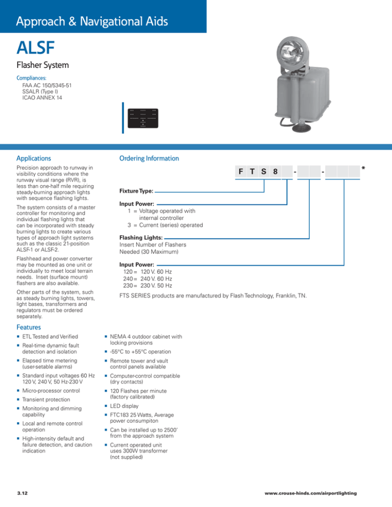
Approach & Navigational Aids ALSF Flasher System Compliances: FAA AC 150/5345-51 SSALR (Type I) ICAO ANNEX 14 Applications Precision approach to runway in visibility conditions where the runway visual range (RVR), is less than one-half mile requiring steady-burning approach lights with sequence flashing lights. The system consists of a master controller for monitoring and individual flashing lights that can be incorporated with steady burning lights to create various types of approach light systems such as the classic 21-position ALSF-1 or ALSF-2. Flashhead and power converter may be mounted as one unit or individually to meet local terrain needs. Inset (surface mount) flashers are also available. Other parts of the system, such as steady burning lights, towers, light bases, transformers and regulators must be ordered separately. Ordering Information F T S 8 - - Fixture Type: Input Power: 1 = Voltage operated with internal controller 3 = Current (series) operated Flashing Lights: Insert Number of Flashers Needed (30 Maximum) Input Power: 120 = 120 V. 60 Hz 240 = 240 V. 60 Hz 230 = 230 V. 50 Hz FTS SERIES products are manufactured by Flash Technology, Franklin, TN. Features ETL Tested and Verified Real-time dynamic fault detection and isolation NEMA 4 outdoor cabinet with locking provisions -55°C to +55°C operation Elapsed time metering (user-setable alarms) Remote tower and vault control panels available Standard input voltages 60 Hz 120 V, 240 V, 50 Hz-230 V Computer-control compatible (dry contacts) Micro-processor control 120 Flashes per minute (factory calibrated) Transient protection Monitoring and dimming capability Local and remote control operation High-intensity default and failure detection, and caution indication 3.12 LED display FTC183 25 Watts, Average power consumpiton Can be installed up to 2500’ from the approach system Current operated unit uses 300W transformer (not supplied) www.crouse-hinds.com/airportlighting * Outline Drawings FRONT VIEW 19(482.6) 4.50(114.3) Ø0.44(11.1) 10.0(254) 4.50(114.3) Ø0.44(11.1) Ø0.05(12.7) 17.8(447.5) 16.0(406.4) Ø0.44(11.1) 18.8(478) Ø0.44(11.1) Dimensions: Inches (mm) Instruction Manual: FTC 183 / FTC 435 Master Flasher Timer Power Supply 29lbs.. 25 lbs.. 13 kg. 11.3 kg. 25.9(658) Shipping Weight: Ø0.75 (19) Ø0.75 (19) Ø1.06 (26.99) BOTTOM VIEW Ø0.75 (19) 6.0 (153) Standard Sequence Flasher System Components Item Part Number Fuse, Power, MDL2A PCB100 Control Board VRI Varistor 120 V Relay, Alarm PCB200 Panel Board 4900342 2471912 6901079 4900501 2472001 Renewal Parts Description Part Number Description Part Number Clamp, Lens (FH400) Flash Tube FT 101 (FH400) Flash Tube FT 101 (FH800) Lens (FH400) Post, Ceramic (FH800) 3893201 8384329* 4901700* 8743701 5900842 RC Network RC101 (FH400 & FH800) Retaining Bezel (FH800) Spacer, Ceramic (FH400) Terminal Screw Lug (FH400) Trigger Transformer (FH400 & FH800) 1403411 3735202 5900844 3379102 8288201 Home Office: United States – +1 860-683-4300 International Offices: Canada • China • Dubai • Mexico • Brazil 3.13
