Deadbreak Apparatus Connectors G600-52-1
advertisement
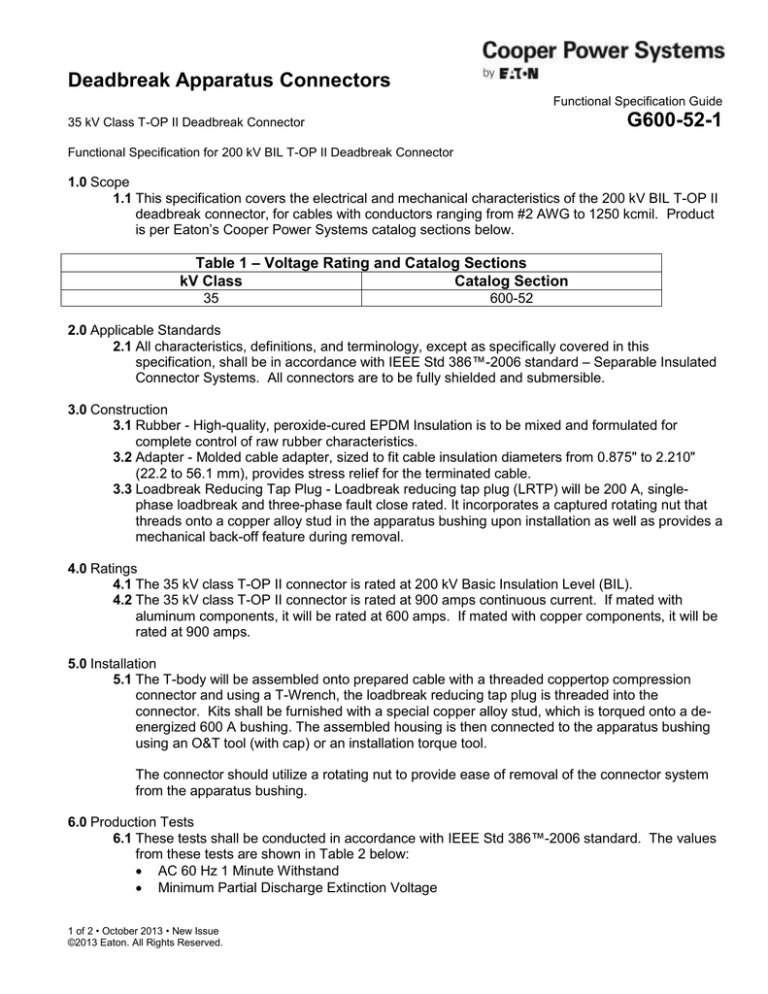
Deadbreak Apparatus Connectors Functional Specification Guide G600-52-1 35 kV Class T-OP II Deadbreak Connector Functional Specification for 200 kV BIL T-OP II Deadbreak Connector 1.0 Scope 1.1 This specification covers the electrical and mechanical characteristics of the 200 kV BIL T-OP II deadbreak connector, for cables with conductors ranging from #2 AWG to 1250 kcmil. Product is per Eaton’s Cooper Power Systems catalog sections below. Table 1 – Voltage Rating and Catalog Sections kV Class Catalog Section 35 600-52 2.0 Applicable Standards 2.1 All characteristics, definitions, and terminology, except as specifically covered in this specification, shall be in accordance with IEEE Std 386™-2006 standard – Separable Insulated Connector Systems. All connectors are to be fully shielded and submersible. 3.0 Construction 3.1 Rubber - High-quality, peroxide-cured EPDM Insulation is to be mixed and formulated for complete control of raw rubber characteristics. 3.2 Adapter - Molded cable adapter, sized to fit cable insulation diameters from 0.875" to 2.210" (22.2 to 56.1 mm), provides stress relief for the terminated cable. 3.3 Loadbreak Reducing Tap Plug - Loadbreak reducing tap plug (LRTP) will be 200 A, singlephase loadbreak and three-phase fault close rated. It incorporates a captured rotating nut that threads onto a copper alloy stud in the apparatus bushing upon installation as well as provides a mechanical back-off feature during removal. 4.0 Ratings 4.1 The 35 kV class T-OP II connector is rated at 200 kV Basic Insulation Level (BIL). 4.2 The 35 kV class T-OP II connector is rated at 900 amps continuous current. If mated with aluminum components, it will be rated at 600 amps. If mated with copper components, it will be rated at 900 amps. 5.0 Installation 5.1 The T-body will be assembled onto prepared cable with a threaded coppertop compression connector and using a T-Wrench, the loadbreak reducing tap plug is threaded into the connector. Kits shall be furnished with a special copper alloy stud, which is torqued onto a deenergized 600 A bushing. The assembled housing is then connected to the apparatus bushing using an O&T tool (with cap) or an installation torque tool. The connector should utilize a rotating nut to provide ease of removal of the connector system from the apparatus bushing. 6.0 Production Tests 6.1 These tests shall be conducted in accordance with IEEE Std 386™-2006 standard. The values from these tests are shown in Table 2 below: AC 60 Hz 1 Minute Withstand Minimum Partial Discharge Extinction Voltage 1 of 2 • October 2013 • New Issue ©2013 Eaton. All Rights Reserved. 200 kV BIL T-OP II Deadbreak Connector System G600-52-1 Table 2 – Voltage Ratings and Test Results kV Class AC Withstand (kV) Min. PD Extinction Voltage (kV) 35 70.0 26.0 6.2 The following tests shall be conducted in accordance with manufacturer requirements: Physical Inspection Periodic Dissection Periodic Fluoroscopic Analysis 7.0 Optional Features Protective Cap Capacitive Test Point All Copper Connector Cold Shrink Kit Shield Adapter Kit T-Wrench Operating and Test/Torque Tool Socket Drive Tool 8.0 Approved Manufacturers 8.1 Eaton’s Cooper Power Systems – Pewaukee, WI 2 of 2 • October 2013 • New Issue ©2013 Eaton. All Rights Reserved.
