Deadbreak Connectors
Catalog Data
Effective April 2015
Supersedes 600-34 October 2012
CA650044EN
COOPER POWER
SERIES
600 A 15 and 25 kV class U-OP™
visible break connector system
General
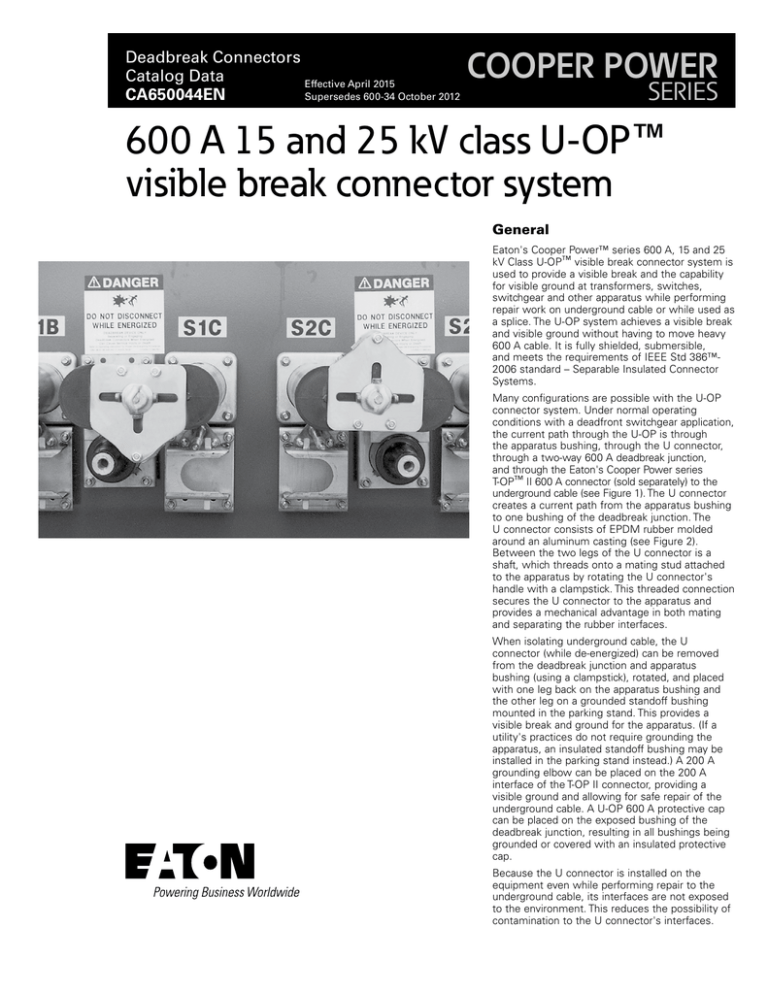
Eaton's Cooper Power™ series 600 A, 15 and 25
kV Class U-OP™ visible break connector system is
used to provide a visible break and the capability
for visible ground at transformers, switches,
switchgear and other apparatus while performing
repair work on underground cable or while used as
a splice. The U-OP system achieves a visible break
and visible ground without having to move heavy
600 A cable. It is fully shielded, submersible,
and meets the requirements of IEEE Std 386™2006 standard – Separable Insulated Connector
Systems.
Many configurations are possible with the U-OP
connector system. Under normal operating
conditions with a deadfront switchgear application,
the current path through the U-OP is through
the apparatus bushing, through the U connector,
through a two-way 600 A deadbreak junction,
and through the Eaton's Cooper Power series
T-OP™ II 600 A connector (sold separately) to the
underground cable (see Figure 1). The U connector
creates a current path from the apparatus bushing
to one bushing of the deadbreak junction. The
U connector consists of EPDM rubber molded
around an aluminum casting (see Figure 2).
Between the two legs of the U connector is a
shaft, which threads onto a mating stud attached
to the apparatus by rotating the U connector's
handle with a clampstick. This threaded connection
secures the U connector to the apparatus and
provides a mechanical advantage in both mating
and separating the rubber interfaces.
When isolating underground cable, the U
connector (while de-energized) can be removed
from the deadbreak junction and apparatus
bushing (using a clampstick), rotated, and placed
with one leg back on the apparatus bushing and
the other leg on a grounded standoff bushing
mounted in the parking stand. This provides a
visible break and ground for the apparatus. (If a
utility's practices do not require grounding the
apparatus, an insulated standoff bushing may be
installed in the parking stand instead.) A 200 A
grounding elbow can be placed on the 200 A
interface of the T-OP II connector, providing a
visible ground and allowing for safe repair of the
underground cable. A U-OP 600 A protective cap
can be placed on the exposed bushing of the
deadbreak junction, resulting in all bushings being
grounded or covered with an insulated protective
cap.
Because the U connector is installed on the
equipment even while performing repair to the
underground cable, its interfaces are not exposed
to the environment. This reduces the possibility of
contamination to the U connector's interfaces.
Catalog Data CA650044EN
600 A 15 and 25 kV class U-OP visible break connector system
Effective April 2015
U Connector
Apparatus Bushing
Parking Stand
Current Path
Through U-OP
Connector System
(
)
T-OP II Connector
2 Bushing 600 A Deadbreak Junction
Figure 1. The U-OP connector system in a typical pad-mounted switchgear application.
Figure 2. The U connector.
2
www.eaton.com/cooperpowerseries
Catalog Data CA650044EN
600 A 15 and 25 kV class U-OP visible break connector system
Effective April 2015
The U-OP connector system is available with a two-way 600 A
junction. The 200 A three-phase rated loadbreak interface on the
T-OP II connector provides a means for obtaining a live test as
well as a convenient location for an Eaton's Cooper Power series
M.O.V.E. arrester.
Production tests
Tests are conducted in accordance with IEEE Std 386™-2006
standard.
•
ac 60 Hz 1 Minute Withstand
• 40 kV
•
Minimum Corona Voltage Level
• 19 kV
Tests are conducted in accordance with Eaton requirements.
•
Physical Inspection
•
Periodic Dissection
•
Periodic Fluoroscopic Analysis
Installation
One leg of the U connector is 3 inches longer to allow the U-OP
connector system to be used with different types of bushings.
For example, welded bushings stick out a different height off the
apparatus' frontplate than clamped bushings do. During installation,
the deadbreak junction and the parking stand, which are mounted on
studs welded to the frontplate, need to be adjusted to the correct
distance off the frontplate to allow the U connector to be properly
installed. Eaton recommends its Cooper Power series alignment
gauges to assist in installing the deadbreak junction and parking
stand correctly.
The U-OP connector system can be retrofitted to many apparatus.
There are two options for installing the deadbreak junction and
parking stand onto studs. One option is to weld studs to the
frontplate. The other option is to purchase a retrofit plate that already
has studs welded to it in the proper positions. Please contact your
Eaton representative for more information on retrofitting the U-OP
connector to your apparatus.
Refer to Service Information S600-14-1 600 A U-OP Visible Break
Connector System Operation Instructions for details on mounting
the U-OP connector system.
Table 1. Voltage Ratings and Characteristics
Description
kV
Standard Voltage Class
25
Maximum Rating Phase-to-Ground
15.2
ac 60 Hz 1 Minute Withstand
40
dc 15 Minute Withstand
78
BIL and Full Wave Crest
125
Minimum Corona Voltage Level
19
Table 2. Current Ratings and Characteristics
Ordering information
Table 3. U-OP Kit
Description
Catalog Number
U-OP Connector Kit (Aluminum)
UOP625
Each U-OP Connector Kit contains:
•
Molded Rubber U Component
•
2-Way 600 A Deadbreak Junction
•
Parking Stand
•
U-OP Stud
•
Hardware Kit
Description
Amperes
Continuous
600 A rms
4 Hour Overload
900 A rms
•
Silicone Lubricant
Short Time
25,000 A rms symmetrical for 10 cycles
•
Installation Instructions Sheet
10,000 A rms symmetrical for 3.0 s
The T-OP II connector system is ordered separately.
Current ratings and characteristics are in accordance with IEEE Std 386™-2006 standard.
www.eaton.com/cooperpowerseries
3
Catalog Data CA650044EN
600 A 15 and 25 kV class U-OP visible break connector system
Effective April 2015
Eaton
1000 Eaton Boulevard
Cleveland, OH 44122
United States
Eaton.com
Eaton’s Cooper Power Systems Division
2300 Badger Drive
Waukesha, WI 53188
United States
Eaton.com/cooperpowerseries
© 2015 Eaton
All Rights Reserved
Printed in USA
Publication No. CA650044EN
Eaton, Cooper Power, U-OP, and T-OP are
valuable trademarks of Eaton in the U.S. and
other countries. You are not permitted to use
these trademarks without the prior written
consent of Eaton.
IEEE Std 386™-2006 standard is a trademark
of the Institute of Electrical and Electronics
Engineers, Inc., (IEEE). This publication/product
is not endorsed or approved by the IEEE.
For Eaton's Cooper Power series U-OP product
information call 1-877-277-4636 or visit:
www.eaton.com/cooperpowerseries.

