DS Receptacles (DS96, DS222, DS290) Installation & Maintenance Information IF 1695 APPLICATION
advertisement
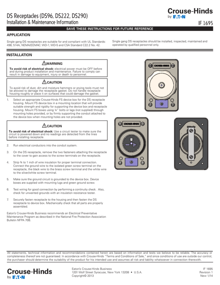
DS Receptacles (DS96, DS222, DS290) Installation & Maintenance Information IF 1695 SAVE THESE INSTRUCTIONS FOR FUTURE REFERENCE APPLICATION Single gang DS receptacles are suitable for and compliant with UL Standards: 498; 514A, NEMA/EEMAC: WD-1; WD-5 and CSA Standard C22.2 No. 42. Single gang DS receptacles should be installed, inspected, maintained and operated by qualified personnel only. INSTALLATION WARNING To avoid risk of electrical shock: electrical power must be OFF before and during product installation and maintenance. Failure to comply can result in damage to equipment, injury or death to personnel. caution To avoid risk of dust, dirt and moisture hammers or prying tools must not be allowed to damage the receptacle gasket. Do not handle receptacle housing roughly or place it on surfaces that could damage the gasket. 1. Select an appropriate Crouse-Hinds FS device box for the DS receptacle housing. Mount FS device box in a mounting location that will provide suitable strength and rigidity for supporting the device box and receptacle housing. Mount FS boxes using ¼” bolts or lags (not supplied) through mounting holes provided, or by firmly supporting the conduit attached to the device box when mounting holes are not provided. caution To avoid risk of electrical shock: Use a circuit tester to make sure the circuit is powered down and no readings are detected from the lines before installing receptacle. 2. Run electrical conductors into the conduit system. 3. On the DS receptacle, remove the two fasteners attaching the receptacle to the cover to gain access to the screw terminals on the receptacle. 4. Strip ¾ to 1 inch of wire insulation for proper terminal connection. Connect the ground wire to the isolated green screw terminal on the receptacle, the black wire to the brass screw terminal and the white wire to the silver/white screw terminal. 5. Make sure the ground circuit is grounded to the device box. Device boxes are supplied with mounting lugs and green ground screw. 6. Test wiring for good connection by performing a continuity check. Also, check for unwanted grounds with an insulation resistance tester. 7. Securely fasten receptacle to the housing and then fasten the DS receptacle to device box. Mechanically check that all parts are properly assembled. Eaton’s Crouse-Hinds Business recommends an Electrical Preventative Maintenance Program as described in the National Fire Protection Association Bulletin NFPA 70B. All statements, technical information and recommendations contained herein are based on information and tests we believe to be reliable. The accuracy or completeness thereof are not guaranteed. In accordance with Crouse-Hinds “Terms and Conditions of Sale,” and since conditions of use are outside our control, the purchaser should determine the suitability of the product for his intended use and assumes all risk and liability whatsoever in connection therewith. Eaton’s Crouse-Hinds Business 1201 Wolf Street Syracuse, New York 13208 • U.S.A. Copyright© 2013 IF 1695 Revision 1 New 1/14
