Application Specification
ANSI C136.41-2013
Rotatable Dimming Receptacles
114-32148
20 JAN 16 Rev B
NOTE
All numerical values are in metric units [with U.S. customary units in brackets]. Dimensions are in millimeters [and inches].
Unless otherwise specified, dimensions have a tolerance of ±0.13 [±.005] and angles have a tolerance of ±2°. Figures and
illustrations are for identification only and are not drawn to scale.
1. INTRODUCTION
This specification covers the requirements for application of ANSI C136.41-2013 Rotatable Dimming
Receptacles typically used for roadway and area lighting. All contacts are pre-installed into the receptacle
housing and pre-crimped with 305 mm (12.0 in.) lead-wire, with 14 AWG stranded wire used on the three line
voltage AC circuits and 18 AWG wire used on the four signal dimming control voltage DC circuits. Receptacle
assemblies are available with both 105ºC and 150ºC rated wire. Receptacle assemblies are also available with
either 2 or 4 dimming control pad-style contacts.
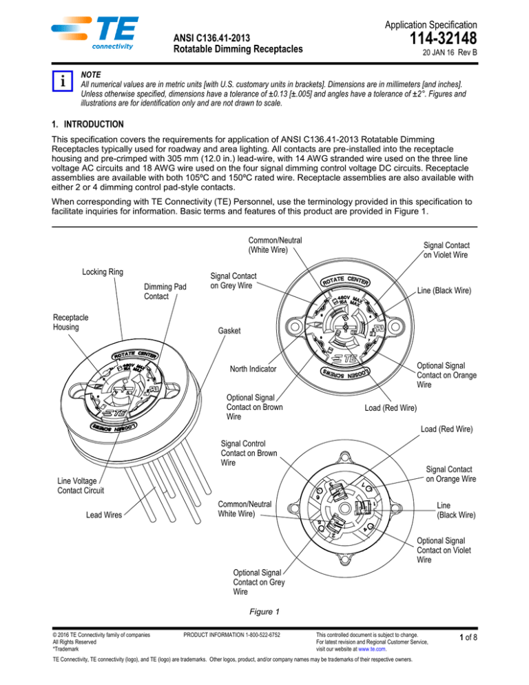
When corresponding with TE Connectivity (TE) Personnel, use the terminology provided in this specification to
facilitate inquiries for information. Basic terms and features of this product are provided in Figure 1.
Common/Neutral
(White Wire)
Locking Ring
Dimming Pad
Contact
Receptacle
Housing
Signal Contact
on Violet Wire
Signal Contact
on Grey Wire
Line (Black Wire)
Gasket
Optional Signal
Contact on Orange
Wire
North Indicator
Optional Signal
Contact on Brown
Wire
Load (Red Wire)
Load (Red Wire)
Signal Control
Contact on Brown
Wire
Signal Contact
on Orange Wire
Line Voltage
Contact Circuit
Lead Wires
Common/Neutral
White Wire)
Line
(Black Wire)
Optional Signal
Contact on Violet
Wire
Optional Signal
Contact on Grey
Wire
Figure 1
© 2016 TE Connectivity family of companies
All Rights Reserved
*Trademark
PRODUCT INFORMATION 1-800-522-6752
This controlled document is subject to change.
For latest revision and Regional Customer Service,
visit our website at www.te.com.
TE Connectivity, TE connectivity (logo), and TE (logo) are trademarks. Other logos, product, and/or company names may be trademarks of their respective owners.
1 of 8
114-32148
2. REFERENCE MATERIAL
2.1. Revision Summary
Added new text to Paragraph 3.6.A. and new artwork and information to Figure 4
2.2. Customer Assistance
Reference Product Base Part Number 2213627-[ ] and Product Code K50 are representative of the ANSI
C136.41-2013 Rotatable Dimming Receptacles. Use of these numbers will identify the product line and help
you to obtain product and tooling information. Such information can be obtained through a local TE
Representative, by visiting our website at www.te.com, or by calling PRODUCT INFORMATION at the number
at the bottom of page 1.
2.3. Drawings
Customer Drawings for product part numbers are available from the service network. If there is a conflict
between the information contained in the Customer Drawings and this specification or with any other technical
documentation supplied, the information contained in the Customer Drawings takes priority.
2.4. Specifications
Product Specification 108-32059 provides product performance and test information for the
ANSI C136.41-2013 Dimming Receptacle.
3. REQUIREMENTS
3.1. Safety
Perform all wiring of receptacle with power turned OFF.
3.2. Limitations
The connectors are designed to operate in a temperature range of -40° to 85°C [-40° to 185°F].
3.3. Material
The housing is made of UL 94V-0 rated thermoplastic. The line voltage contacts are made of phosphorous
bronze plated overall with tin. Dimming pad contacts are made of brass with gold plating in contact pad area,
tin plated in wire crimp area with nickel under-plate on entire contact.
3.4. Storage
A. Ultraviolet Light
Prolonged exposure to ultraviolet light may deteriorate the chemical composition used in the product
material.
B. Shelf Life
The product should remain in the shipping containers until ready for use to prevent deformation to
components. The product should be used on a first in, first out basis to avoid storage contamination that
could adversely affect performance.
C. Chemical Exposure
Do not store product near any chemical listed below as they may cause stress corrosion cracking in the
material.
Alkalies
Ammonia
Citrates
Phosphates Citrates
Sulfur Compounds
Amines
Carbonates
Nitrites
Sulfur Nitrites
Tartrates
Rev B
2 of 8
114-32148
3.5. Shipping
A. Handling
The receptacle assembly is supplied with a mating face cap to provide protection during shipping.
Dimming contact pads are lubricated with an electrical contact lubricant; therefore after removal of the
protective cap, avoid contact with the dimming contact pads which could remove the electrical contact
lubricant.
B. Separation of Locking Ring from Assembly
If the locking ring becomes separated from the main assembly during shipping, it can be re-attached using
the procedure shown in Figure 2. The ring is snapped onto the center receptacle housing with the TE logo
aligned with either screw hole. The locking ring can then be rotated until it stops so that it is well retained
on the center receptacle housing.
Align the TE logo with one
of the screw holes, then
snap on the lock ring.
Turn the lock ring full
clockwise (or turn the
center housing full counterclockwise).
The lock ring will stop with
the North indicator adjacent
to the screw hole.
Figure 2
3.6. Receptacle Mounting
A. Mounting (Figure 3)
A flat surface shall be provided on luminaire housing to mount receptacle assembly. The flatness of the
mounting surface shall be within 0.5 mm, including any surface irregularities from painting or plating. To
provide water-tight mounting, it is highly recommended that the TE gasket (p/n 2213626-1) be used to
seal surfaces between receptacle assembly and luminaire housing. This TE gasket is available kitted with
the receptacle assembly or can be bulk ordered separately. The receptacle housing has two mounting
holes which accept #8 size flat-head recessed screws with 82° bevel heads. Screws of the appropriate
length and type must be determined by the luminaire manufacturer. When using the TE Gasket, a screw
torque of 1.0 to 2.0 N-m is recommended. Do NOT exceed 3.0 N-m. If the luminaire has a built in raised
sealing ring on the mounting surface, please consult with TE engineering for assistance for a custom
gasket design.
CAUTION
If a non-TE gasket is used, it is the responsibility of the installer to determine the mounting screw torque to ensure a watertight seal between the receptacle and luminaire housing. Please use customer print 2213626 for the gasket reference design.
The following gasket features are critical to the proper operation and sealing of the rotatable dimming socket: the gasket
thickness, gasket inner diameter, and the gasket durometer (40 Shore A hardness).
Rev B
3 of 8
114-32148
CAUTION
Never mount the Rotating Dimming Receptacle without a gasket present or an improper gasket design with an undersized
inner diameter. Damage may occur to the locking ring when the screws are torqued to specification.
#8 Mounting
Screws (2)
Gasket
Luminaire
Housing
Figure 3
B. Mounting Hole Pattern
The recommended mounting hole pattern is shown in Figure 4.
49.22 ±0.13
Recommended
Mounting Layout
Ø69 Min.
NOTE: Inside this zone (69 mm
dia.), the mounting surface shall
have the flatness within 0.5 mm.
If the mounting surface has a built
in sealing ring inside this zone,
please contact TE engineering.
Ø5.56 +0.25/0 (2X)
Ø35.05 +0.50/0
Figure 4
C. Mounting Location and Orientation
Locate the receptacle where artificial light cannot fall on the mating photocell causing it to turn off or cycle
(on and off) at night. If possible, orient the receptacle so the North indicator points North.
D. Workmanship
The housing must not be damaged in any way. There shall be no nicked wire insulation.
3.7. Wire Connections and Diagram
A. Wire Connections
The receptacle wires must be appropriately spliced with the correct line voltage power or dimming signal
source. When splicing lead wires with crimp-style splices, wire nuts, etc., ensure the proper size splicing
connector per the manufacturer’s recommendation is being used.
Rev B
4 of 8
114-32148
DANGER
Extreme caution must be taken to ensure that power is OFF prior to disconnecting or connecting any wires to prevent
electrical shock.
NOTE
All wire connections must be electrically insulated.
B. Wiring Diagram
The receptacle wires must be appropriately spliced with the correct line voltage power or dimming signal
source. Refer to the wiring diagram example shown in Figure 5. Wiring diagram shown is for general
information only. Luminaire manufacturer must determine wiring diagram based upon their ballast/driver
with dimming control components.
Wiring Diagram
(For General Information Only)
Receptacle
Assembly
Terminal
Block
Black
Black
White
Red
Violet
Grey
Orange
Brown
Luminaire
Housing
Grey
Violet
Black
White
White
Line
Brown (Optional)
Orange (Optional)
Connector
Point (7X)
Dim Dim +
Internal Ballast/Driver with
Dimming Control
Load
Figure 5
3.8. Strain Relief
It is recommended that a means be provided to support the wire bundle extending away from the receptacle
assembly to prevent inadvertent application of high force to the wire bundle from transmitting into the
wire/connector interface. The suggested strain relief method is to use a cable tie and anchor mounted inside
the luminaire.
3.9. Rotating the Mounted Receptacle
Once the light fixture is installed in the field, it is easy to rotate the receptacle so the North indicator is aimed
properly. Loosen the mounting screws just enough so the center receptacle housing rotates freely in the
locking ring. Use a screwdriver to aim the center receptacle housing so the North indicator points in the desired
direction (typically due North). The Rotatable Dimming Receptacle is designed to limit the total rotation to 355°
with a stop feature. If the desired direction can’t be achieved by turning clockwise due to the stop feature,
simply turn the center receptacle housing counter-clockwise to the desired position. Once the desired aiming is
achieved, the mounting screws can then be tightened to the proper torque. See Figure 6.
Rev B
5 of 8
114-32148
Loosen (do not remove)
mounting screws.
Use the screwdriver to turn
the center housing to the
proper aiming.
Re-tighten the screws to
the proper torque.
Figure 6
3.10. Mating and Un-mating Photocell to Receptacle
Align photocell blades with receptacle power contact circuits. Note that the neutral photocell blade is larger
than the line and load blades, providing mating polarization. After properly aligning the blades to the receptacle
power contact circuits, push downward until the photocell is bottomed on the receptacle’s mating surface,
slightly compressing gasket of the photocell. Then complete mating by twisting the photocell in a clockwise
direction. The photocell will lock into position. To un-mate, reverse the aforementioned mating process.
Reference Figure 7.
1.
Push Downward
2. Twist Clockwise to Lock
Photocell
Figure 7
Rev B
6 of 8
114-32148
3.11. Replacement and Repair
The contacts and housings are not repairable. DO NOT use an assembly with damaged or defective contacts
and/or housings. If damaged, replace the receptacle assembly with a new one.
4. QUALIFICATIONS
ANSI C136.41-2013 Rotatable Dimming Receptacles have not yet been sent for agency evaluation and testing.
5. TOOLING
No special tooling is require for the installation of this product line.
Rev B
7 of 8
114-32148
6. VISUAL AID
The illustration below shows a typical application of ANSI C136.41-2013 Dimming Receptacles. This illustration
should be used by production personnel to ensure a correctly applied product. Applications which DO NOT
appear correct should be inspected using the information in the preceding pages of this specification and in the
instructional material shipped with the product or tooling.
SCREWS MUST BE
PROPERLY TIGHTENED
TO ENSURE A RAINTIGHT SEAL
RECEPTACLE HOUSING
MUST NOT BE
CRACKED OR
DAMAGED IN ANY WAY
DIMMING CONTACT PAD
SURFACE MUST NOT BE
DAMAGED IN ANY WAY
LUMINAIRE HOUSING
AND GASKET MUST BE
PROPERLY INSTALLED
FIGURE 7. VISUAL AID
Rev B
8 of 8

