From: AAAI-02 Proceedings. Copyright © 2002, AAAI (www.aaai.org). All rights reserved.
Localizing while Mapping: A Segment Approach
Andrew J. Martignoni III and William D. Smart
Department of Computer Science
Washington University
One Brookings Drive
St. Louis, MO 63130
United States of America
{ajm7, wds}@cs.wustl.edu
http://www.cs.wustl.edu/∼ajm7/map
Localization in mobile robotics is a well studied problem in many environments (Thrun et al. 2000; Hinkel &
Knieriemen 1988; Burgard et al. 1999; Rencken 1993).
Map building with occupancy grids (probabilistic finite element maps of the environment) is also fairly well understood. However, trying to accomplish both localization and
mapping at once has proven to be a difficult task. Updating
a map with new sensor information before determining the
correct adjustment for the starting point and heading can be
disastrous, since it changes parts of the map which were not
meant to be changed, thus the next iteration is using an incorrect map to determine the adjustment to the pose, which
results in greater error, and the cycle continues.
This research hopes to solve this problem by performing localization on higher-level objects computed from the
raw sensor readings. Initially these higher-level objects are
line segments and common structures, such as office doors,
but any object which can be detected from a single sensor
reading can be used to help the localization process. Objects which require more complex analysis can be found and
placed in the map, but will not be used for localization. The
higher-level features provide for better localization in an unknown environment, through simpler correspondence with
existing map objects. In addition, once the data from the
robot’s sensors have been turned into a map with humanidentifiable features, the map can easily be augmented with
additional information.
Much of the previous work in this area uses occupancy
grids (Moravec & Elfes 1985; Elfes 1987), or pixel based
maps. Pixels in occupancy grids represent a certain size area
of the environment, and represents the probability that the
area contains an object. Other work (Park & Kender 1995;
Kuipers & Byun 1991) uses a topological system where
landmarks are picked out of the environment and added as
nodes on a graph which is then used for navigation.
Pixel-based maps tend to limit the size of the area that
can be covered, and the actual data in the image tends to
be sparse because the map representations are a fixed size
and shape and do not necessarily match the size and shape
of the area to be mapped. An object map (of line segments
or other detected features) has no such bounds since only the
end points of a segment (or similar real-valued data for other
c 2002, American Association for Artificial IntelliCopyright gence (www.aaai.org). All rights reserved.
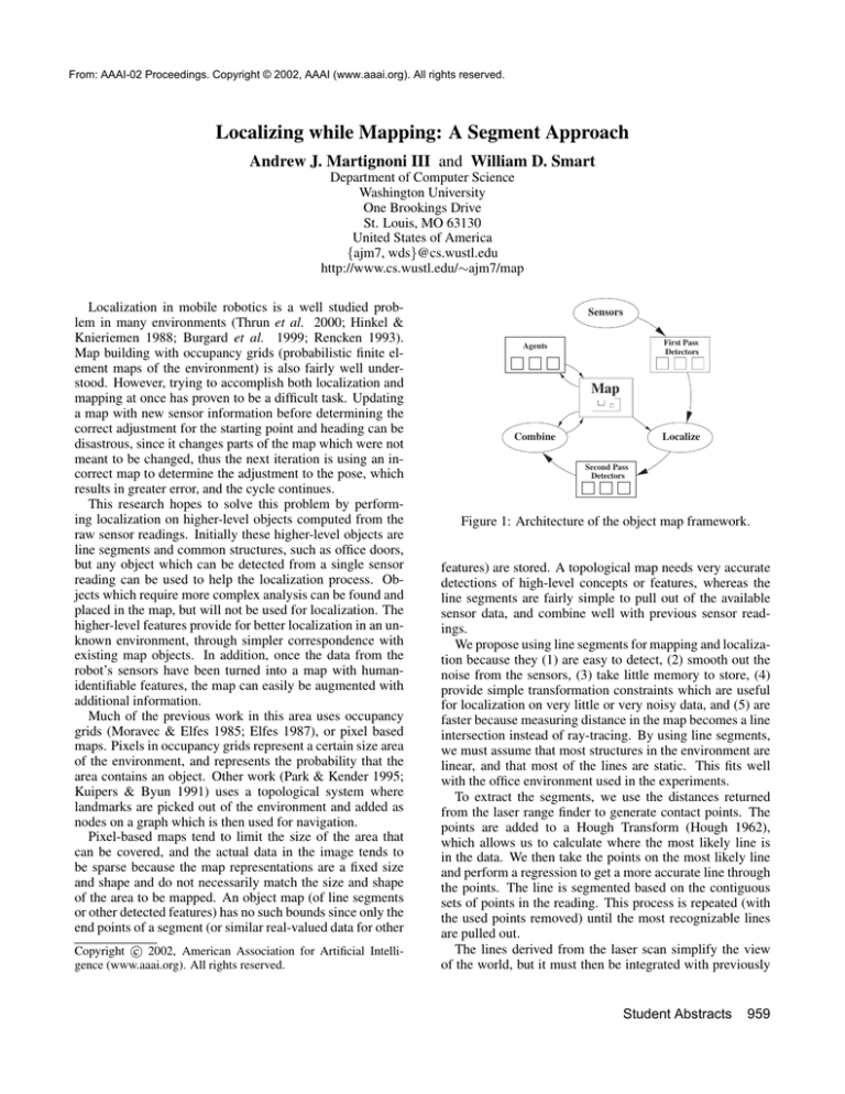
Sensors
First Pass
Detectors
Agents
Map
Combine
Localize
Second Pass
Detectors
Figure 1: Architecture of the object map framework.
features) are stored. A topological map needs very accurate
detections of high-level concepts or features, whereas the
line segments are fairly simple to pull out of the available
sensor data, and combine well with previous sensor readings.
We propose using line segments for mapping and localization because they (1) are easy to detect, (2) smooth out the
noise from the sensors, (3) take little memory to store, (4)
provide simple transformation constraints which are useful
for localization on very little or very noisy data, and (5) are
faster because measuring distance in the map becomes a line
intersection instead of ray-tracing. By using line segments,
we must assume that most structures in the environment are
linear, and that most of the lines are static. This fits well
with the office environment used in the experiments.
To extract the segments, we use the distances returned
from the laser range finder to generate contact points. The
points are added to a Hough Transform (Hough 1962),
which allows us to calculate where the most likely line is
in the data. We then take the points on the most likely line
and perform a regression to get a more accurate line through
the points. The line is segmented based on the contiguous
sets of points in the reading. This process is repeated (with
the used points removed) until the most recognizable lines
are pulled out.
The lines derived from the laser scan simplify the view
of the world, but it must then be integrated with previously
Student Abstracts
959
Path
Doorwells
Lines
5m
Figure 2: An object map generated from sensor data.
acquired data which is represented in the map. The lines
detected in the first reading are simply added to the map
at the origin. Subsequent readings must be registered with
the existing map before adding. As the robot moves, the
wheels may slip and cause the heading to vary by several
degrees over the course of a hallway. The line segments
in the new reading are matched with their closest matching
line segments in the existing map. The final heading correction is determined by histogramming angle differences.
This method has proven to be very robust in our experiments. Once the heading is determined, the robot’s 2D location must be determined. To accomplish this, observe that
the matched line segments are all within a few degrees of
parallel. To move these lines together with the corresponding line in the map, we wish to move the midpoint of the
new line onto the line in the map there are infinitely many
possible vectors (corrections) which move the midpoint to
any point on the map line, we add a constraint on the vector
to a system of equations and solve it in a least squared error
fashion. Solving the system yields the best-fit values of ux
and uy which represent a 2D location adjustment. This localization relies on the position estimate being close enough
to the real position that the new line segments match up with
their counterparts in the map. This assumption holds for a
reasonable range of speeds with our hardware. Without a
somewhat accurate estimate of the motion of the robot, this
method would have to rely on global searches, and would be
much slower and prone to error in environments with a lot
of similarities (such as office buildings). Once the pose has
been updated, the new reading’s line segments are merged
with the existing map. The current combination method
tends to weight new readings and the map line segments
equally.
Currently, the system will find and detect lines and doors
in an office environment. We are currently adding agents
which look for other types of objects, such as people, trash
cans, or other important features, especially when they may
be built on the features which are already detected. Each
new type of object will also improve the localization, because the distance metric uses object type to improve matching performance.
We hope to introduce better update methods, including
960
Student Abstracts
those which may split line segments based on new information, or tracking moving objects in the environment. Also,
finding features could be automated by carrying around
points from laser readings which were not used for any objects in a “point bag” object which could later be matched
against other objects using a clustering algorithm. This
could make additional feature detectors simply a matter of
giving a name for a set of objects that were already discovered and categorized.
The advantage of a direct object representation is that
each object can be tagged with information, such as “Mike’s
Office” or “Door001”, which could also lead to logic based
reasoning and navigation.
References
Burgard, W.; Fox, D.; Jans, H.; Matenar, C.; and Thrun,
S. 1999. Sonar-based mapping of large-scale mobile robot
environments using EM. In Proceedings of the Sixteenth
International Conference on Machine Learning (ICML).
McGraw-Hill.
Elfes, A. 1987. Sonar-based real-world mapping and
navigation. IEEE Journal on Robotics and Automation
3(3):249–265.
Hinkel, R., and Knieriemen, T. 1988. Environment perception with a laser radar in a fast moving robot. In Proceedings of Symposium on Robot Control, 68.1–68.7.
Hough, P. 1962. Methods and means for recognizing complex patterns. U.S. Patent 3069654.
Kuipers, B. J., and Byun, Y.-T. 1991. A robot exploration and mapping strategy based on a semantic hierarchy
of spatial representations. Robotics and Autonomus Systems 8:46–63.
Moravec, H. P., and Elfes, A. 1985. High-resolution maps
from wide angle sonar. In Proceedings of IEEE International Conference on Robotics and Automation, 116–121.
Park, I., and Kender, J. 1995. Topological direction-giving
and visual navigation in large environments. Artificial Intelligence 78(1-2):355–395.
Rencken, W. D. 1993. Concurrent localisation and map
building for mobile robots using ultrasonic sensors. In Proceedings of the IEEE/RSJ International Conference on Intelligent Robots and Systems, 2129–2197.
Thrun, S.; Fox, D.; Burgard, W.; and Dellaert, F. 2000. Robust monte carlo localization for mobile robots. Artificial
Intelligence 101:99–141.

