Massachusetts Institute of Technology
advertisement
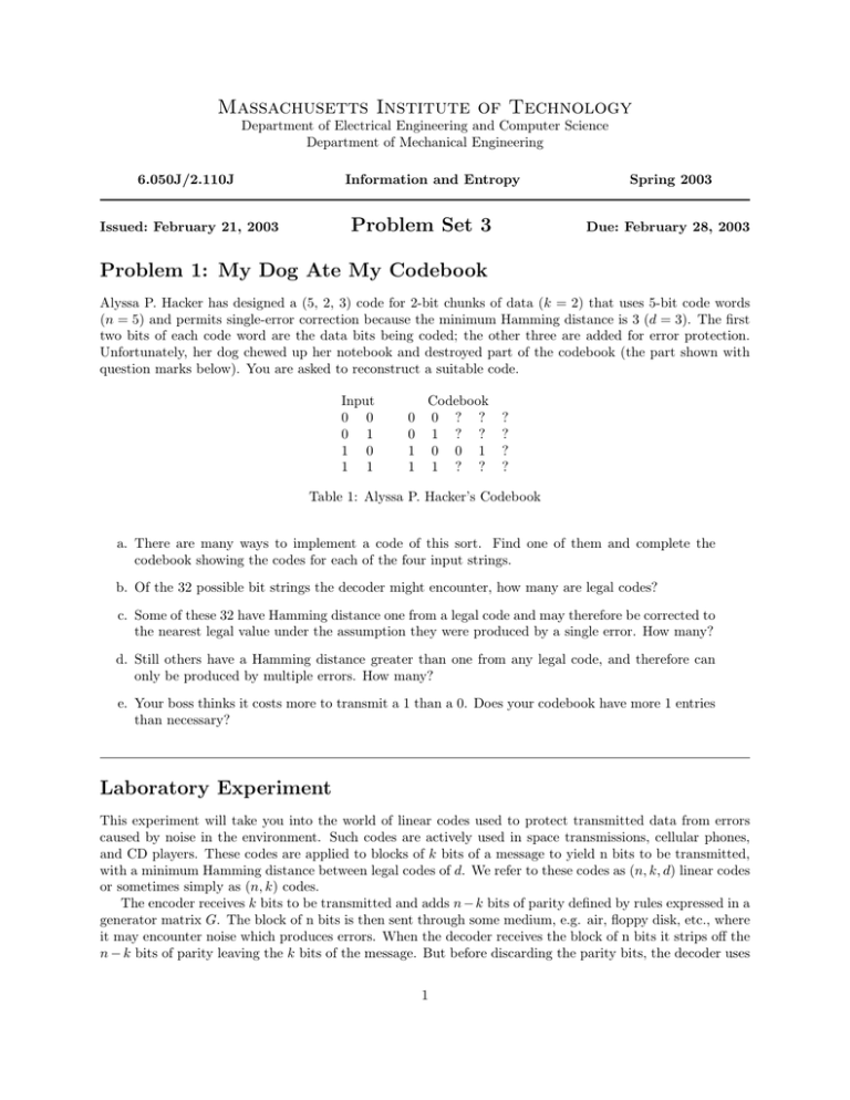
Massachusetts Institute of Technology Department of Electrical Engineering and Computer Science Department of Mechanical Engineering 6.050J/2.110J Information and Entropy Problem Set 3 Issued: February 21, 2003 Spring 2003 Due: February 28, 2003 Problem 1: My Dog Ate My Codebook Alyssa P. Hacker has designed a (5, 2, 3) code for 2­bit chunks of data (k = 2) that uses 5­bit code words (n = 5) and permits single­error correction because the minimum Hamming distance is 3 (d = 3). The first two bits of each code word are the data bits being coded; the other three are added for error protection. Unfortunately, her dog chewed up her notebook and destroyed part of the codebook (the part shown with question marks below). You are asked to reconstruct a suitable code. Input 0 0 0 1 1 0 1 1 0 0 1 1 Codebook 0 ? ? 1 ? ? 0 0 1 1 ? ? ? ? ? ? Table 1: Alyssa P. Hacker’s Codebook a. There are many ways to implement a code of this sort. Find one of them and complete the codebook showing the codes for each of the four input strings. b. Of the 32 possible bit strings the decoder might encounter, how many are legal codes? c. Some of these 32 have Hamming distance one from a legal code and may therefore be corrected to the nearest legal value under the assumption they were produced by a single error. How many? d. Still others have a Hamming distance greater than one from any legal code, and therefore can only be produced by multiple errors. How many? e. Your boss thinks it costs more to transmit a 1 than a 0. Does your codebook have more 1 entries than necessary? Laboratory Experiment This experiment will take you into the world of linear codes used to protect transmitted data from errors caused by noise in the environment. Such codes are actively used in space transmissions, cellular phones, and CD players. These codes are applied to blocks of k bits of a message to yield n bits to be transmitted, with a minimum Hamming distance between legal codes of d. We refer to these codes as (n, k, d) linear codes or sometimes simply as (n, k) codes. The encoder receives k bits to be transmitted and adds n − k bits of parity defined by rules expressed in a generator matrix G. The block of n bits is then sent through some medium, e.g. air, floppy disk, etc., where it may encounter noise which produces errors. When the decoder receives the block of n bits it strips off the n − k bits of parity leaving the k bits of the message. But before discarding the parity bits, the decoder uses 1 Problem Set 3 2 them to correct any errors it finds. The number of errors that can be detected or corrected depends on the linear codes used to generate the parity bits. The decoder uses a parity­check matrix H. Consider the (7, 4, 3) Hamming code: 4 bits for the message and 3 bits for the parity codes totaling up to 7 bits. The following is one possible generator matrix G and the corresponding parity check matrix H. ⎡ ⎤ ⎡ ⎤ 1 0 0 0 0 1 1 0 0 0 1 1 1 1 ⎢ 0 1 0 0 1 0 1 ⎥ ⎥ ⎣ ⎦ G=⎢ (3–1) ⎣ 0 0 1 0 1 1 0 ⎦ H= 0 1 1 0 0 1 1 1 0 1 0 1 0 1 0 0 0 1 1 1 1 Bits Parity 1 Parity 2 Parity 3 Message 2 3 4 x x x x x 1 Parity 6 7 x x x x x x 5 x Table 2: Parity Table 2 is based on the matrix H but labels the first four bits as message and the rest as parity. These codes are called linear codes because the operations are done by matrix multiplication (a special form that uses XOR operations in place of normal arithmetic multiplication and addition). Let’s multiply the matrix G by the four­bit message A to produce a seven­bit codeword: >> A = [1 1 0 1]; >> B = A*G B = 1 1 0 1 2 2 3 Oops. Note that this is not what we want for the 7­bit codeword. MATLAB did conventional matrix multiplication. We have to change all even values to 0 and odd values to 1 to get what we want, [1 1 0 1 0 0 1]. This can be done several ways, for example by using mod­2 remainders >> B = mod(B, 2) B = 1 1 0 1 0 0 1 Notice that in B the first 4 bits are A and the last 3 bits are the parity. This is because our generator G matrix has this property (the first four columns of G form an identity matrix). There are other generator matrices that still yield a (7, 4, 3) Hamming code but place the bits of the original message in other positions. The matrix H is used by the decoder to discover any errors: >> C = mod(B*H’, 2) C = 0 0 0 where the apostrophe signifies a matrix transpose (the matrix formed by flipping a matrix about its main diagonal – H is a 3 × 7 matrix and H � is a 7 × 3 matrix). The fact that C is entirely 0 means there were no errors to correct, so the decoder simply strips off the parity bits. Now let us assume that an error has occurred in bit position 3 so the decoder receives the message as [1 1 1 1 0 0 1] rather than [1 1 0 1 0 0 1]. Now, Problem Set 3 3 >> B(3) = ~B(3); >> C = mod(B*H’, 2) C = 0 1 1 Due to our choice of H, the result gives us 0 1 1 which in decimal is 3, the bit position of the error. Use MATLAB to reproduce these results and try one or two other messages. Then you will be ready for Problem 2. Do not include this lab experiment as part of what you turn in. Hint: you can define a matrix like G by something like G = [1 0 0 0 0 1 1; 0 1 0 0 1 0 1;...] Problem 2: A Different Hamming Code There are many possible Hamming code generator matrices G and corresponding decode matrices H. The example in the laboratory experiment above had the useful property that the binary representation of the location of the error is the result of using the H matrix. This property was a result of the fact that H was made of columns with these binary representations in order. In a more general case, (see Error Correction with Hamming Codes) the bit pattern produced by multi­ plying the received code word by H can be compared with the columns of H, and the location of the fault inferred by which column if any is matched. For this problem use these alternate matrices (different from the matrices used in the Laboratory Experiment above): ⎡ ⎤ ⎡ ⎤ 1 0 0 0 1 0 1 1 1 1 0 1 0 0 ⎢ 0 1 0 0 1 1 0 ⎥ ⎥ ⎣ ⎦ G=⎢ (3–2) ⎣ 0 0 1 0 1 1 1 ⎦H = 0 1 1 1 0 1 0 1 0 1 1 0 0 1 0 0 0 1 0 1 1 Hint: It is easiest to do this problem using MATLAB, but if you prefer you can use paper and pencil. If you do use MATLAB, put your code in the file ps3p2.m and all your comments in your diary named ps3diary. a. Generate a test pattern PATTERN which consists of all possible four­bit messages. Make this in the form of a matrix with four columns and 16 rows. b. Generate the “codebook” which is a matrix containing in each row the seven­bit codeword from the corresponding row of PATTERN. You can get this with a single matrix multiplication followed by the mod operation. Call this matrix CODEBOOK. c. How many errors can the decoder using the matrix H correct? How many errors can it detect if it does no corrections? d. Verify that this (7, 4, 3) Hamming code works by using it to transmit and receive 3 messages of your choice, without errors. In this context, “transmit and receive” means select a four­bit word, find its codebook entry by using the matrix G, check it for errors using the matrix H, and if necessary make corrections. e. Repeat with the same messages but this time introduce one error in each message and verify that the use of the matrix H reveals the location of the error (remember that to identify which bit is at fault you compare with the columns of H. In one of these cases make the error happen in a parity bit. f. Using one of these messages, introduce two errors and see what the decoder does. Compare the original message with the “corrected” one. Problem Set 3 4 Problem 3: Ben’s Best Bet You are designing a product that uses a Rectangular Code of the sort discussed in Chapter 4 of the notes to assure the correctness of a critical byte of information that is being sent over a noisy channel. In your design the byte is broken into two parts and each is protected by its own rectangular code. The design uses ten extra error­protection bits to protect the payload of eight data bits D0 ­ D7, and can correct single errors and detect double errors. D0 D2 PC0 D1 D3 PC1 PR0 PR1 P0 D4 D6 PC2 D5 D7 PC3 PR2 PR3 P1 Table 3: Your Proposed Error Detection Code One of your colleagues, Ben Bitdiddle, has reviewed your design and suggests that you change it so that you do not transmit the parity bits PR0 and PR2, just the six associated with the other rows and columns (PR1, PR3 and PC0 ­ PC3), and the total parity bits (P0 and P1). He says that will be equally effective and more efficient. a. Is Ben’s efficiency higher? What is his code rate? What is yours? b. Can all single errors be corrected with Ben’s design? Either briefly explain why, or provide a counter example. c. Can any double errors be corrected with Ben’s design? Either briefly explain why not, or provide an example. d. Can all double errors be detected and identified as double errors with Ben’s design? Either briefly explain why, or provide a counter example. Turning in Your Solutions If you used MATLAB, you should have 2 files, one M­files and one diary. Name the M­file ps3p2.m and name the diary ps3diary. You may turn in this problem set by e­mailing your M­files and diary. Do this either by attaching them to the e­mail as text files, or by pasting their content directly into the body of the e­mail (if you do the latter, please indicate clearly where each file begins and ends). The deadline for submission is the same no matter which option you choose. Your solutions are due 5:00 PM on Friday, February 28, 2003. Later that day, solutions will be posted on the course website. MIT OpenCourseWare http://ocw.mit.edu 6.050J / 2.110J Information and Entropy Spring 2008 For information about citing these materials or our Terms of Use, visit: http://ocw.mit.edu/terms.
