MASSACHUSETTS INSTITUTE OF TECHNOLOGY Department of Electrical Engineering and Computer Science Issued:
advertisement
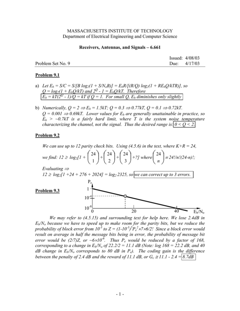
MASSACHUSETTS INSTITUTE OF TECHNOLOGY Department of Electrical Engineering and Computer Science Receivers, Antennas, and Signals – 6.661 Issued: 4/08/03 Due: 4/17/03 Problem Set No. 9 Problem 9.1 a) Let Eb = S/C = S/[B log2(1 + S/NoB)] = EbR/[(R/Q) log2(1 + REbQ/kTR)], so Q = log2(1 + EbQ/kT) and 2Q - 1 = EbQ/kT. Therefore Eb = kT(2Q - 1)/Q = kT if Q = 1. For small Q, Eb diminishes only slightly b) Numerically, Q = 2 ⇒ Eb = 1.5kT; Q = 0.3 ⇒ 0.77kT, Q = 0.1 ⇒ 0.72kT. Q = 0.001 ⇒ 0.69kT. Lower values for Eb are generally unattainable in practice, so Eb > ~0.7kT is a fairly hard limit, where T is the system noise temperature characterizing the channel, not the signal. Thus the desired range is: 0 < Q < 2. Problem 9.2 We can use up to 12 parity check bits. Using (4.5.6) in the text, where K+R = 24, we find: 12 ≥ log2[1 + ⎛⎜ 24 ⎞⎟ + ⎛⎜ 24 ⎞⎟ + ⎛⎜ 24 ⎞⎟ +?] where ⎛⎜ 24 ⎞⎟ ≡ 24!/n!(24-n)!; ⎝ 1 ⎠ ⎝ 2 ⎠ ⎝ 3 ⎠ ⎝ n ⎠ Evaluating ⇒ 12 ≥ log2[1 +24 + 276 + 2024] = log2 2325, so we can correct up to 3 errors. Pe Problem 9.3 1 10-4 10-8 40 20 0 Eb/No We may refer to (4.5.15) and surrounding text for help here. We lose 2.4dB in Eb/No because we have to speed up to make room for the parity bits, but we reduce the probability of block error from 10-3 to Z = (1-10-3)5Pe2×7×6/2! Since a block error would result on average in half the message bits being in error, the probability of message bit error would be (2/7)Z, or ~6×10⁻⁶. Thus Pe would be reduced by a factor of 168, corresponding to a change in Eb/No of 22.2/2 = 11.1 dB (Note: log 168 = 22.2 dB, and 40 dB change in Eb/No corresponds to 80 dB in Pe). The coding gain is the difference between the penalty of 2.4 dB and the reward of 11.1 dB, or Gc ≅ 11.1 - 2.4 = 8.7dB - 1 - Problem 9.4 b) The noise n1(t) can be considered to be the environmental noise, while n2(t) is postsmoothing and can include the sensor noise, photon shot noise, read-out noise, and quantization noise. Lumping the sensor noise with n1(t) is awkward because n1(t) precedes convolution. a) Let x,y be coordinates referenced to the focal plane. We can consider f(x,y) to correspond to the lens blurring function (arbitrarily chosen to be narrow) and g(x,y) to be the focal plane response function of each CCD pixel; i(x,y) represents the spacing of the pixels and r(x,y) corresponds to the viewer's visual response function (assumed blurry). Thus we might have: i(x,y) r(x,y) f(x,y) g(x,y) i(x,y) x,y ~15 microns Problem 9.5 The received power must support the desired output SNR, which is 20 + 40 dB (⇒10 ). But for SSBSC, which performs the same as DSBSC, the necessary S/Nout is <s2(t)>(Pc/2NoW) where No = kTs/2, Ts = 4000K, k = 1.38×10⁻²³, and W = 104 Hz. <s2(t)> = 0.5 for pure sine waves at maximum amplitude, and 1 for square waves. The maximum average received power is then Pc<s2(t)> = 2NoW×106 = 2×1.38×10-23×4000×104×106 = 1.1×10⁻⁹ [W]. If we allow for a 70-dB path loss, then the average transmitter power is ~1.1×10⁻²W, or ~10 milliwatts, which is reasonable. 6 Problem 9.6 a) Referring to Figure 4.7-10 and associated text, the FM threshold S/N for β* = 10 is approximately 18 dB, so Pc/BkT = 101.8 and Pr = Pc > 63×2W(1 + β*)kT = 63×2×104(1+10)1.38×10-23×4000 = 7.7×10⁻¹³ W received and 7.7×10⁻⁶ W transmitted b) The output SNR requirement is 20+40 = 60 dB, where Sout/Nout = Pc<s2>3β*2/2NoW = 106, so Pc ≅ 106×2×1.38×10-23× 4000×104/(0.5×3×100) = 7.36×10⁻¹²W; Pt ≅ 7.4×10⁻⁵W. c) The requirements for Pt are a factor of ~9.6 greater than the FM threshold, so we could reduce β* slightly to x, where 102/x2 = 9.6, so the new x = β* could be 3.23, but then the only margin left would be due to the fact that the FM threshold drops slightly with β*. -2-
